
Method and apparatus for validating OBD repairs

a technology for obd repairs and repair methods, applied in the direction of instrumentation, structural/machine measurement, vehicle testing, etc., can solve the problems of vehicle failure, vehicle failure automatically, and not always a safe assumption

Inactive Publication Date: 2007-04-19
GANZCORP INVESTMENTS
View PDF22 Cites 78 Cited by
  • Summary
  • Abstract
  • Description
  • Claims
  • Application Information

AI Technical Summary

Benefits of technology

[0017] In accordance with yet another aspect of the present invention, a computer readable medium having computer-executable instructions including receiving data from a scan tool that characterizes operating conditions of at least one control module of a vehicle, cont...

Problems solved by technology

Otherwise, the vehicle would fail and the owner would have to have the vehicle repaired and retested.
When a vehicle goes in for testing, if the MIL is illuminated at that time, the vehicle automatically fails.
As some Drive Cycles require a specific set of conditions that are not feasible in urban areas (i.e. speed above 60-mph and throttle opening of greater than 60%), this is not always a safe assumption.
Moreover, the repair technician cannot be certain that his repair has solved the problem when the vehicle leaves his shop without resetting monitors as the vehicle's on-board computer cannot detect a problem until a monitor is in a “Complete” or “Ready” state.
This results in a return trip to the repair shop to get a proper repair of the emission system.

Method used


Image

  • Method and apparatus for validating OBD repairs
  • Method and apparatus for validating OBD repairs
  • Method and apparatus for validating OBD repairs

Examples


Embodiment Construction

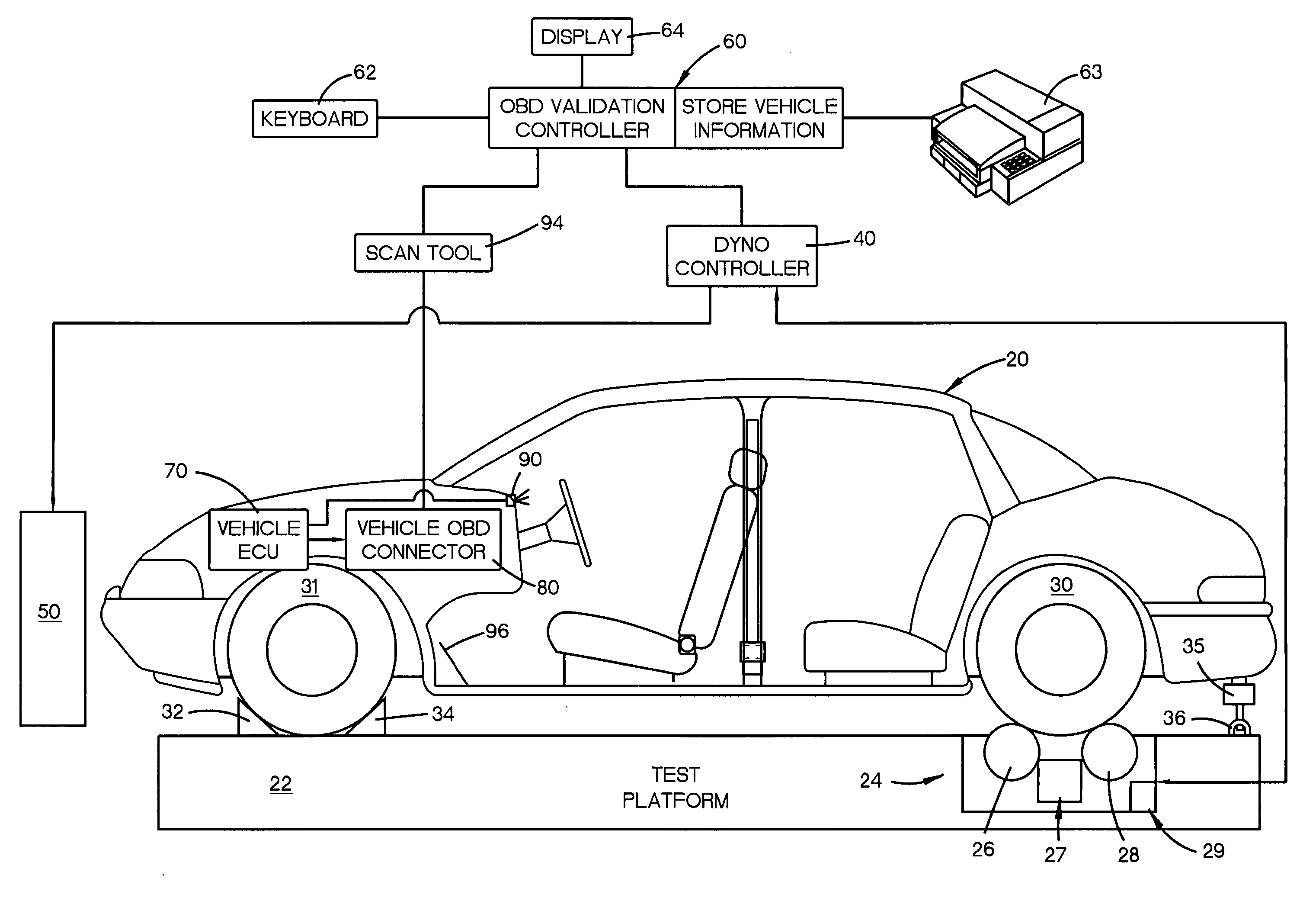
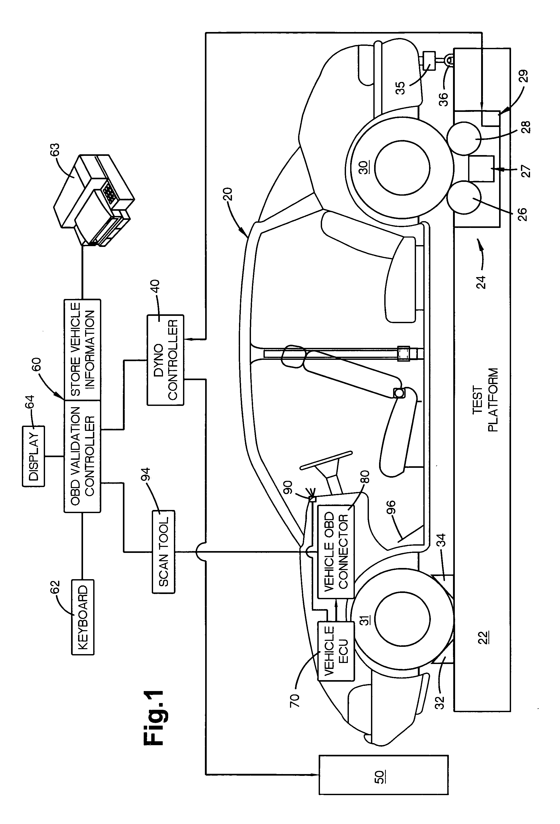
[0025] Referring to FIG. 1, a rear wheel drive vehicle 20, is driven onto a test platform 22 having a controllable dynamometer 24 with rollers 26, 28 so that the vehicle's rear wheels 30 operatively engage the rollers 26, 28 in a known manner. Moveable front 32 and rear 34 wheel chock restraint devices are positioned in front of and behind, respectively, the front wheels 31 to prevent the vehicle 20 from leaving the dynamometer. A ratchet strap 35 is attached and tighten between the vehicle 20 and the I-hook 36 attached to the test platform to secure the vehicle while operating on the dynamometer. The purpose of the dynamometer 24 is to simulate road load forces for the vehicle 20 as the vehicle 20 is being “driven” on the dynamometer. The dynamometer 24 may be of any known type such as any eddy current brake type that can apply a variable load in response to a control signal. The dynamometer may also have fixed, variable, or selectable rotating inertia attached or simulated via a d...


PUM


Abstract

A method is provided for validating emissions component conditions of a vehicle including the steps of operatively placing drivable wheel hubs of the vehicle under load so that the vehicle drive wheel hubs may be driven without vehicle movement and running the vehicle through an associated drive cycle associated with that vehicle. The method further includes the steps of determining if monitored emission components are in a Ready condition at the end of drive cycle, and monitoring for diagnostic trouble codes during and at the end of the drive cycle.

Description

RELATED APPLICATION [0001] This application claims the benefit of U.S. Provisional Application No. 60 / 726,847, filed Oct. 14, 2005, which is herein incorporated by reference in its entirety.TECHNICAL FIELD [0002] The present invention is directed to a method and apparatus for aiding to insure proper emissions related vehicle repairs and is particularly directed to a method and apparatus for validating emissions related vehicle repairs diagnosed via error codes and readiness codes received from a vehicle's on-board computer system through the vehicle's on-board-diagnostic connector or via a wireless interface to the vehicle's on-board computer. BACKGROUND OF THE INVENTION [0003] Vehicle's emissions systems have been tested by government or state agencies in an attempt to insure compliance with federally mandated standards designed to reduce emissions that contribute to air pollution. Vehicles are equipped with emissions systems that are configured to reduce harmful emissions. The 199...

Claims


Application Information

Patent Timeline
IPC IPC(8): G01M17/00G06F19/00
CPCG01M15/102
Inventor GANZHORN, DONALD W. JR.CALDWELL, MICHAEL H.
Owner GANZCORP INVESTMENTS
Learn More