Test Output Compaction for Responses with Unknown Values

Inactive Publication Date: 2007-04-19
NEC CORP
View PDF6 Cites 19 Cited by
  • Summary
  • Abstract
  • Description
  • Claims
  • Application Information

AI Technical Summary

Benefits of technology

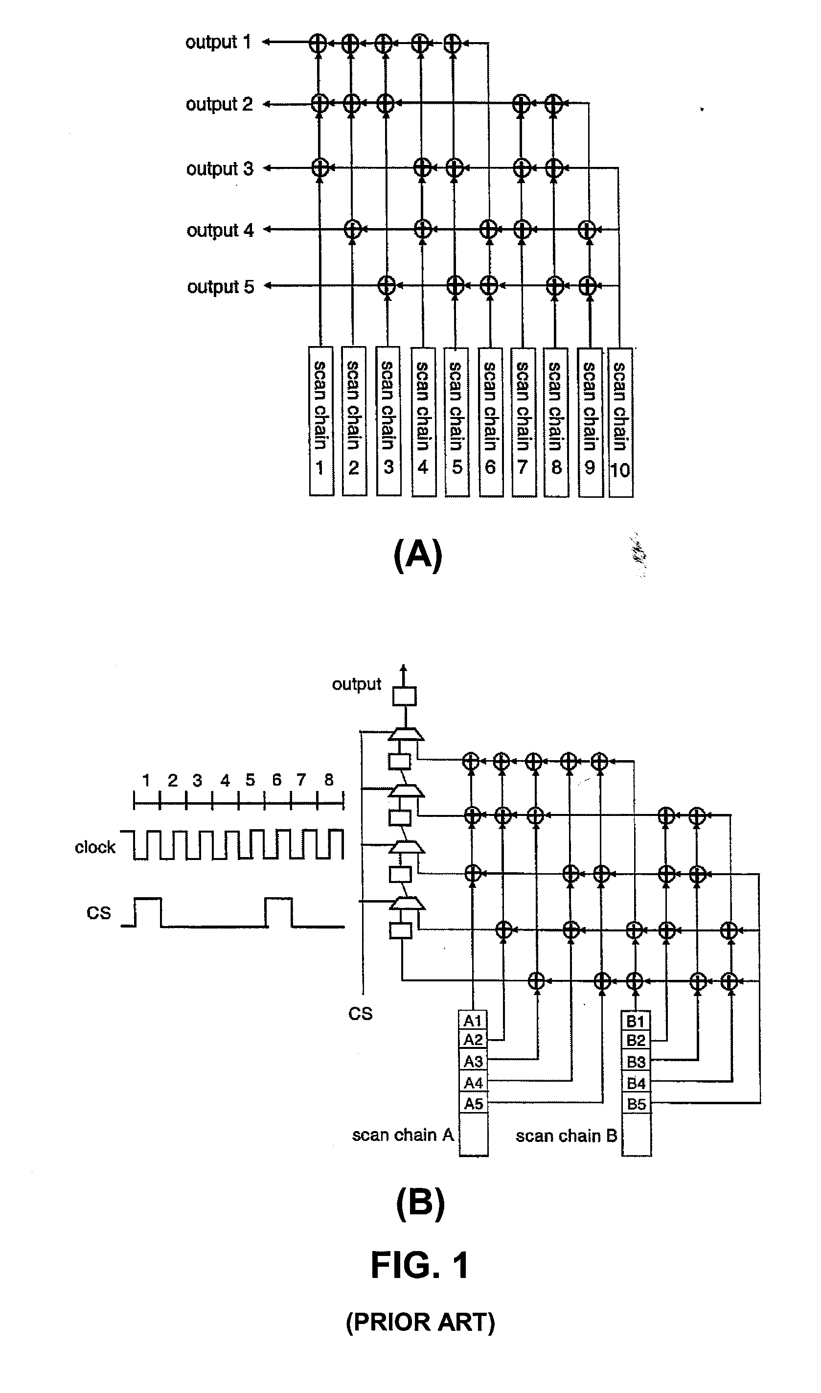
[0006] A spatial compactor design and technique for the compaction of test response data is herein disclosed which advantageously provides a scan-out response with multiple opportunities to be observed on different output channels in one to several scan-shift cycles. The compactor receives test response values from a plurality of scan chains and from different scan-shift cycles within a scan chain. The compactor combines the test response values using a plurality of sub-arrays of logic gates to directly generate output values at a plurality of external outputs, the number of external outputs being less than the number of scan chains. The sub-arrays of logic gates, preferably XOR gates, are arranged so as to minimize the masking of errors in the test response data. Memory elements can be added to a sub-array so as to store the test response data from different scan-shift cycles within a scan chain. The sub-arrays can be represented by a matrix where the number of rows in the matrix is equal to the number of external outputs and the number of columns in the matrix is equal to the number of different scan-shift cycles used within a scan chain. In one embodiment, referred to as a regular-type compactor, each sub-array matrix has a same number of logic gates in each column of the matrix and no two matrices are identical. In a second embodiment, referred to as a flexible-type

Problems solved by technology

Testing of complicated digital logic circuits requires the analysis of a large amount of test response data.
A key barrier to effective output response compaction is the presence of what are referred to as “unknown” values when computing the good-circuit responses.
Unknown values can occur for many reasons: the presence of non-scan flip-

Method used


Image

  • Test Output Compaction for Responses with Unknown Values
  • Test Output Compaction for Responses with Unknown Values
  • Test Output Compaction for Responses with Unknown Values

Examples


Embodiment Construction

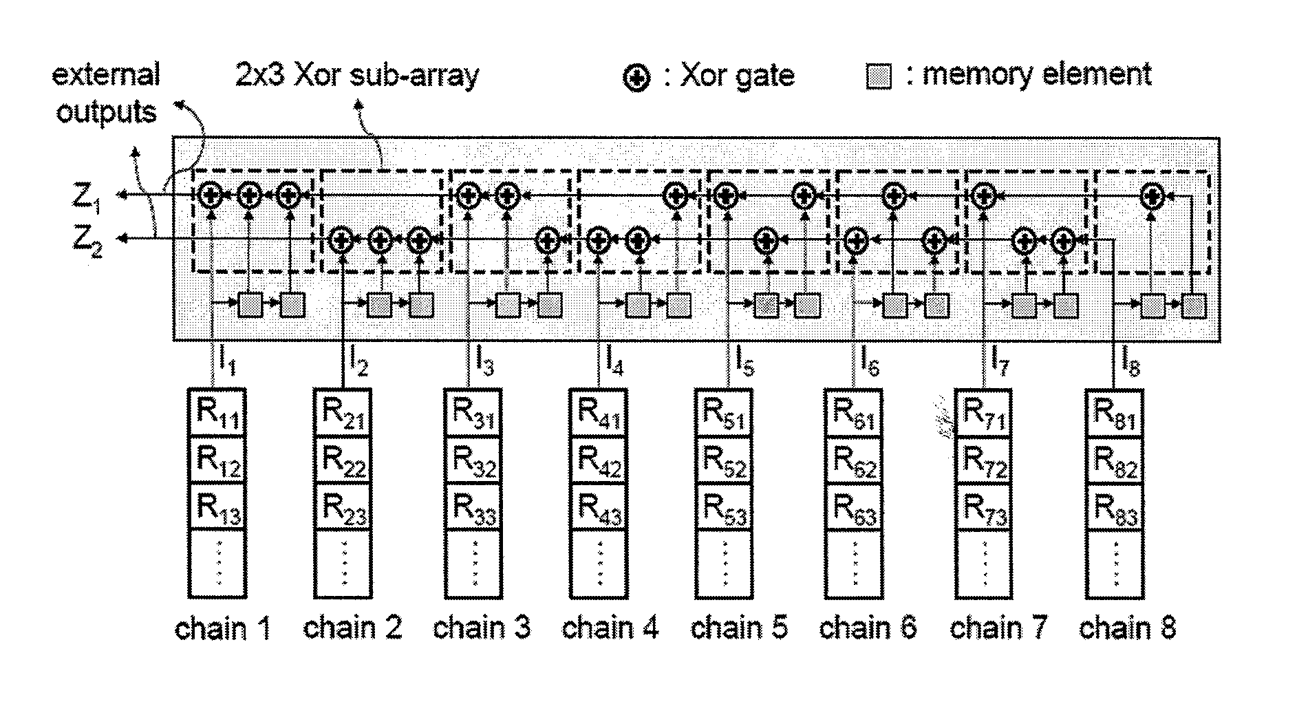
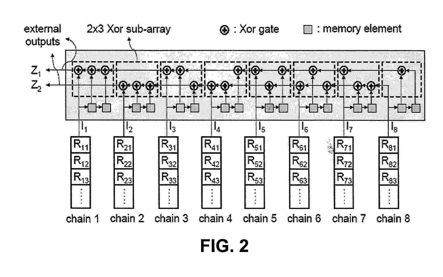
[0018]FIG. 2 is a block diagram depicting an exemplary compactor, arranged in accordance with an embodiment of the present invention. The inventors refer to the compactor 200 as a “Chi-Yun” compactor. The compactor 200 depicted in FIG. 2 illustratively comprises eight inputs 211, . . . , 218 and two external outputs 291, 292. Each input connects to a scan chain 201, . . . , 208 and each external output 291, 292 connects to a tester channel.

[0019] The compactor 200 comprises logic gates, preferably XOR gates, grouped into sub-arrays 221, . . . , 228. For each scan chain 201, . . . , 208, the compactor includes an XOR sub-array and memory elements arranged so as to propagate a response into different external outputs 291, 292 in different scan-shift cycles. The number of rows in a sub-array is equal to the number of external outputs; the number of columns is one more than the number of memory elements used in the sub-array. As depicted in FIG. 2, the input of the first column in an X...


PUM


Abstract

A spatial compactor design and technique for the compaction of test response data is herein disclosed which advantageously provides a scan-out response with multiple opportunities to be observed on different output channels in one to several scan-shift cycles.

Description

[0001] This application claims the benefit of and is a non-provisional of U.S. Provisional Application No. 60 / 722,097, entitled “TEST OUTPUT COMPACTION FOR RESPONSES WITH UNKNOWN VALUES,” filed on Sep. 29, 2005, the contents of which are incorporated by reference herein.BACKGROUND OF THE INVENTION [0002] The present invention is related to testing of logic circuit designs and, in particular, to compaction of test response data. [0003] Testing of complicated digital logic circuits requires the analysis of a large amount of test response data. A variety of output compaction techniques have been devised for reducing the size of test response data stored in test memory. Techniques to reduce output responses can be classified into two basic categories: “spatial compaction” and “temporal compaction.” Temporal compaction compresses output responses over a period of time into a signature, the signature being significantly smaller than the size of even a single uncompressed output response. ...

Claims


Application Information

Patent Timeline
IPC IPC(8): G01R31/28
CPCG01R31/318547
Inventor CHAO, CHIA-TSOWANG, SEONGMOONCHAKRADHAR, SRIMAT T.
Owner NEC CORP
Why Eureka
Try Eureka