Retroreflecting fabrics

a technology of retroreflective fabrics and fabrics, applied in textiles and paper, protective garments, instruments, etc., can solve the problems of limited reflectance, difficult application of retroreflective paints, and limited flexibility of the layers of such paints

Active Publication Date: 2021-09-16
EREZ THERMOPLASTIC PROD AGRI COOP ASSOC LTD
View PDF0 Cites 1 Cited by
  • Summary
  • Abstract
  • Description
  • Claims
  • Application Information

AI Technical Summary

Benefits of technology

[0021]The retroreflecting fabrics of this disclosure typically comprise a top-most layer of said retroreflecting composition, that, as will be explained below, contains a relatively low amount of reflecting particles, e.g. at most 60 wt % out of the total weight of the retroreflective composition. This relatively low amount of reflective particles allows obtaining a surface distribution of the particles of between about 10 and 200 particles per cm2 of fabric; such a low surface density of particles allows for relatively large distances between particles, thus minimizing the masking of the fabric's original color. Namely, in the retroreflecting fabrics of this disclosure satisfactory reflectance is obtained by using a relatively low amount of reflective particles that are distributed over a large surface area.
[0127]In some embodiments, the second polymeric material is applied onto the first bottom layer by calendaring. Prior to calendering (i.e. between steps (d) and (e) or between steps (d′) and (e′)), the process may comprise a step (d1 or d1′) in which the first bottom layer heated. Such heating increases the tackiness of the first bottom layer by either melting its surface or activating the cross-linking agent (if such is used in the first bottom layer), thus facilitating adherence of the second bottom layer to the first bottom layer. According to such embodiments, the first bottom layer may be heated to a temperature of between about 160 to 230° C.

Problems solved by technology

Such fabrics, although providing some degree of reflectivity, provide limited reflectance as often the loading of reflective dye is limited.
When applied to fabrics, such retroreflective paints are often hard to apply due to the absorbability of the fabric.
Further, layers of such paints have limited flexibility, hence often cracking and eventually flaking-off the painted fabric.
Thus, due to their limited flexibility, such paints are often applied onto the fabric in limited areas and / or in the form of patches, significantly limiting the area that can reflect light.
Such masking of color is especially undesired in safety and life-saving articles (such as life-vests), in which the original color of the fabric needs to be maintained (both for allowing detection in daytime and for meeting strict international regulations).
Therefore, such paints are often applied onto very limited areas of the fabric.
Although this increases the retroreflectance of the fabric, the production of such fabrics is often costly and complex, as well as results in limited flexibility of the fabric.
Such application of a mirror layer also often causes change or masking of the fabric's original color.
In most life-saving devices which require light reflectance (e.g. life vests, life rafts, etc.), standard colors or color shades are required which are often unfavorably affected by the presence of mirror-like layers and / or a high concentration of reflective particles.

Method used


Image

  • Retroreflecting fabrics
  • Retroreflecting fabrics
  • Retroreflecting fabrics

Examples


example

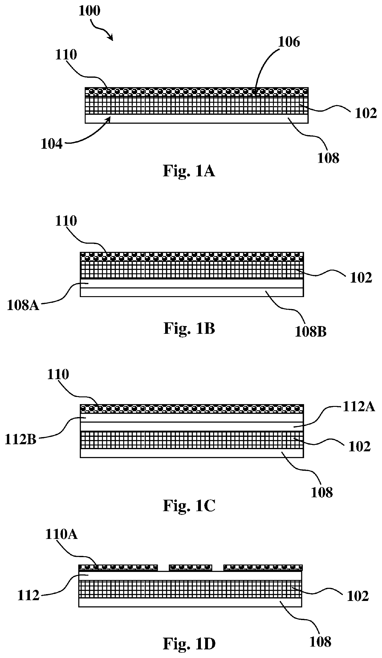
[0169]An exemplary manufacturing process of a retroreflecting fabric suitable for preparing inflatable products (such as life-vests, life-rafts, inflatable boats, etc.) will now be described. It is to be understood that the example is provided in a non-limiting fashion. Similar processes within the scope of the present disclosure may be provided for the manufacturing of different types of retroreflecting fabrics with different functional layers (providing that the top-most layer is a retroreflective layer).

[0170]A first paste comprising 25 wt % polyurethane resin, 50 wt % methylethylketone (MEK) and 25 wt % dimethylformamide (DMF) was prepared by dissolving the polyurethane during mixing for at least 48 hours to afford complete dissolution. Prior to application onto the fabric, app. 2 wt % of an aromatic diisocyanate was added.

[0171]The first paste was applied by a knife-on-air or a knife-on-roll pasting method onto the bottom surface of a nylon fabric having an areal density of app...


PUM

PropertyMeasurementUnit
thicknessaaaaaaaaaa
thicknessaaaaaaaaaa
thicknessaaaaaaaaaa

Abstract

Provided are fabrics having retroreflectivity, products produced therefrom and methods of their manufacture.

Description

TECHNOLOGICAL FIELD[0001]The present disclosure concerns fabrics having retroreflectivity, products produced therefrom and methods of their manufacture.BACKGROUND ART[0002]References considered to be relevant as background to the presently disclosed subject matter are listed below:[0003]EP 2886617[0004]WO 2015 / 171405[0005]U.S. Pat. No. 9,217,817[0006]U.S. Pat. No. 4,763,985[0007]U.S. Pat. No. 4,103,060[0008]WO 99 / 03007[0009]U.S. Pat. No. 5,620,775[0010]Acknowledgement of the above references herein is not to be inferred as meaning that these are in any way relevant to the patentability of the presently disclosed subject matter.BACKGROUND[0011]Reflectance of irradiated light is often used to increase visibility of various objects in various environmental conditions. For example, light reflectance may be used for increasing visibility of objects in dark surroundings (e.g. poorly illuminated environment), detecting / identifying survivors or cargo in searching efforts, warning signs or m...

Claims


Application Information

Patent Timeline
Patent Type & Authority Applications(United States)
IPC IPC(8): A41D31/32D06N3/00G02B5/128
CPCA41D31/325D06N3/0088D06N2209/0876G02B5/128D06N3/0063
Inventor LANTERNARI, DANIELSABAN, YAAKOVCONROY, YARON
Owner EREZ THERMOPLASTIC PROD AGRI COOP ASSOC LTD
Why Eureka
Try Eureka