Method for manufacturing magnetostrictive torque sensor

Inactive Publication Date: 2007-04-26
HONDA MOTOR CO LTD
View PDF1 Cites 21 Cited by
  • Summary
  • Abstract
  • Description
  • Claims
  • Application Information

AI Technical Summary

Benefits of technology

[0014] In the inventive method, the demagnetization step is provided either after or immediately before the step of creating magnetic anisotropy in the magnetostrictive films, and repeated irregular magnetization created in the rotating shaft surface or the magnetostrictive film surfaces by the electroplating step or the magnetic anisotropy formation step are removed to the fullest extent possible. Therefore, effects of irregular magnetization, such as those seen in conventional practice, on the magnetostrictive characteristics of the magnetostrictive films are reduced, and nonuniformities in the sensor sensitivity characteristics during torque sensing are reduced.
[0015] Since the torque sensing characteristics of different magnetostrictive torque sensors are made unifor

Problems solved by technology

Therefore, in a magnetostrictive torque sensor manufactured by a conventional magnetostrictive torque sensor manufacturing method, the magnetic anisotropy characteristics in the magnetostrictive films have been subject to the effects of irregular magnetization created in the rotating shaft surface or the magnetos

Method used


Image

  • Method for manufacturing magnetostrictive torque sensor
  • Method for manufacturing magnetostrictive torque sensor
  • Method for manufacturing magnetostrictive torque sensor

Examples


Example

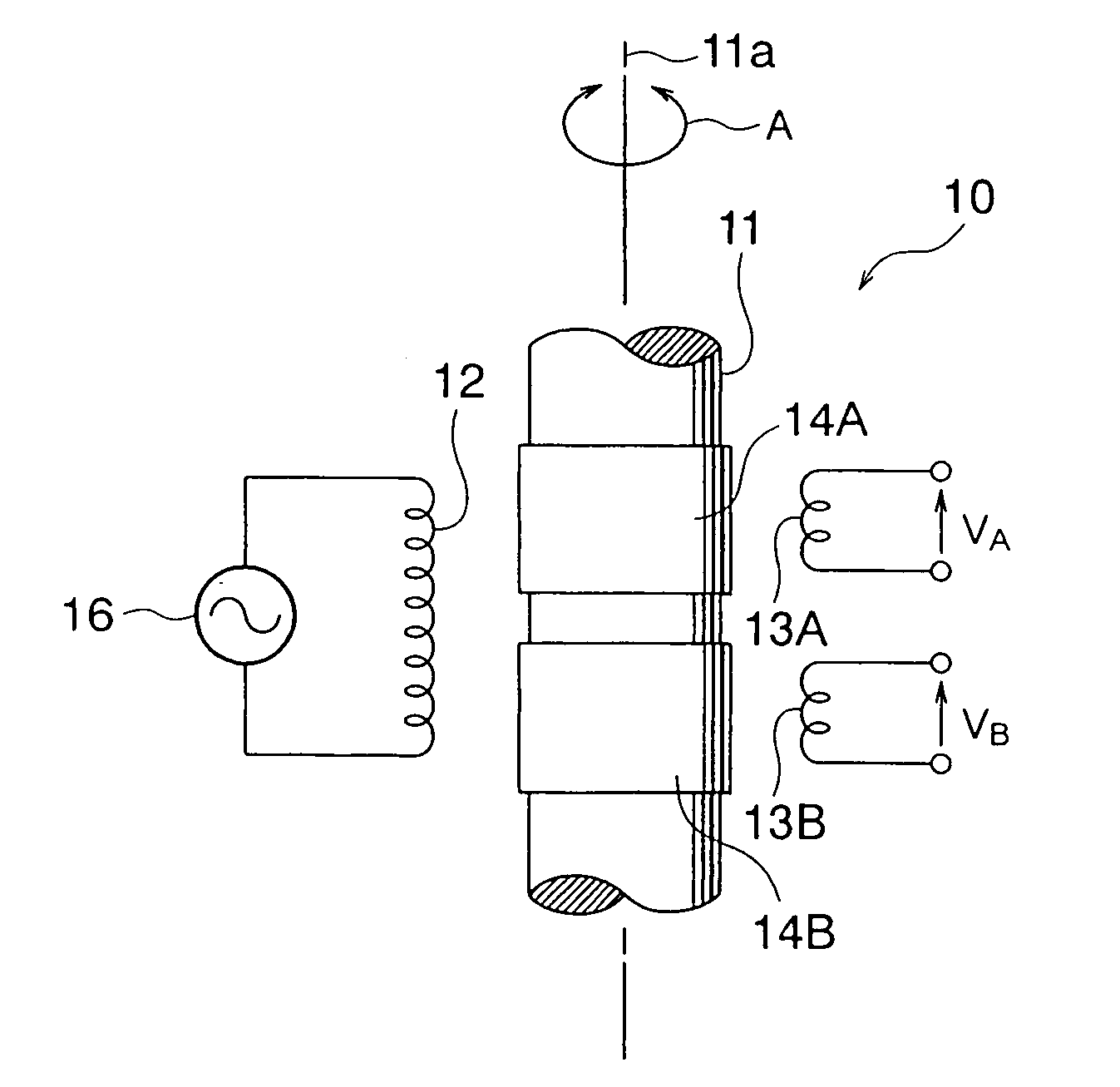
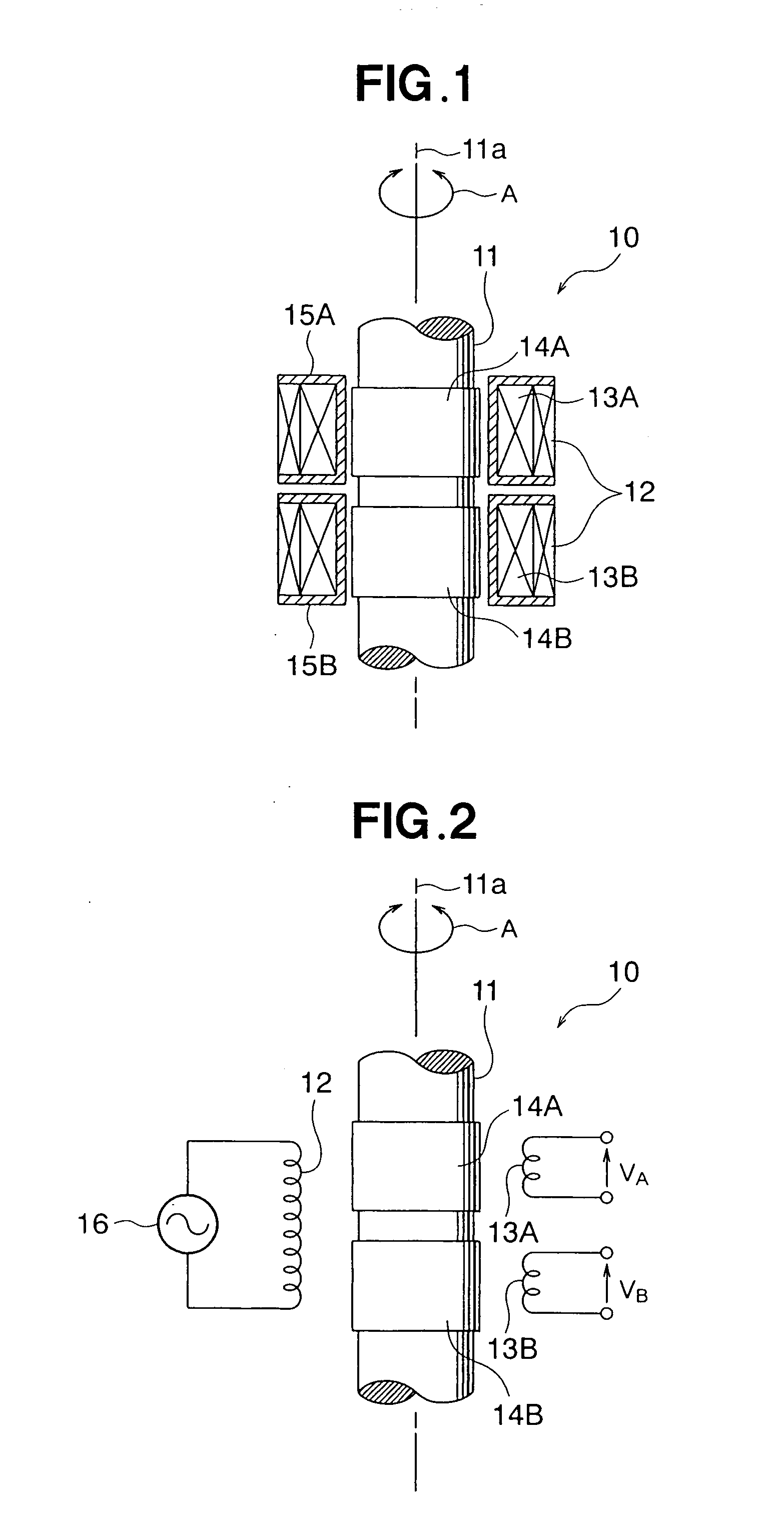
[0033] A magnetostrictive torque sensor will be described with reference to FIGS. 1 through 3. FIGS. 1 through 3 show a structural example of a magnetostrictive torque sensor manufactured by the method for manufacturing a magnetostrictive torque sensor according to the present invention.

[0034] A magnetostrictive torque sensor 10 is configured from a rotating shaft 11, and one excitation coil 12 and two sensor coils 13A, 13B disposed around the periphery of the rotating shaft 11, as shown in FIGS. 1 and 2. For the sake of convenience in the description, the rotating shaft 11 is shown without the top and bottom parts in FIGS. 1 and 2.

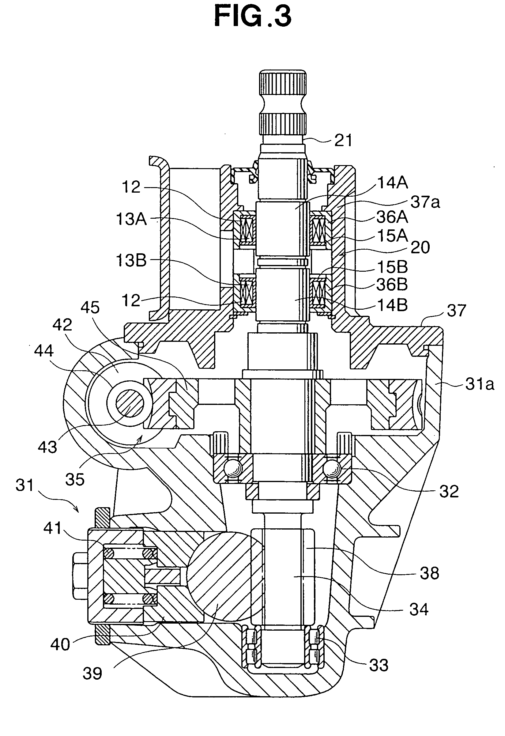
[0035] Referring to the example of utilization shown in FIG. 3, the rotating shaft 11 is configured as part of a steering shaft 21, for example. The rotating shaft 11 is subjected to the rotational force (torque) of right-hand rotation (clockwise) or left-hand rotation (counterclockwise) around the axis 11a, as shown by the arrow A. The rotating shaft 1...


PUM


Abstract

A method for manufacturing a magnetostrictive torque sensor compriseis the steps of forming magnetostrictive films on a rotating shaft of a magneto-strictive torque sensor, creating magnetic anisotropy in the magnetostrictive films formed in the magnetostrictive film formation step, and demagnetizing the rotating shaft. The demagnetization step is provided in any of the stages after the magnetostrictive film formation step, and comprises initializing the remanent magnetism created in the rotating shaft.

Description

FIELD OF THE INVENTION [0001] The present invention relates to a method for manufacturing a magnetostrictive torque sensor, and particularly relates to a method for manufacturing a magnetostrictive torque sensor that is suitable for reducing nonuniformities induced in the sensitivity characteristics of different sensors by magnetizing effects in the various steps, and for increasing the efficiency of assembling the sensor in an electrically powered steering apparatus or the like. BACKGROUND OF THE INVENTION [0002] In an electrically powered steering apparatus that is provided as a steering system in an automobile, for example, a steering torque sensor commonly senses a steering torque applied to a steering shaft from a steering wheel by the steering operation of the driver. In the prior art, the steering torque sensor is normally configured from a torsion bar torque sensor, and magnetostrictive torque sensors have recently been proposed. The steering shaft functions as a rotating sh...

Claims


Application Information

Patent Timeline
IPC IPC(8): G01L3/00
CPCG01L3/102G01L3/103G01L3/105
Inventor KASHIMURA, YUKIYADOI, MIZUHOHARATA, HITOSHIFUKUDA, YUICHIYOSHIMOTO, NOBUHIKO
Owner HONDA MOTOR CO LTD
Why Eureka
Try Eureka