Movement and position identification sensor

a position identification and sensor technology, applied in the field of movement sensors, can solve the problems of inability to fast and parallel functional test of individual sensors, significant disadvantages in production engineering and costs, and multiple contact columns, so as to facilitate free movement, reduce sensor sensitivity, and high resistance

Inactive Publication Date: 2015-01-27
KARLSRUHER INST FUR TECH +1
View PDF16 Cites 2 Cited by
  • Summary
  • Abstract
  • Description
  • Claims
  • Application Information

AI Technical Summary

Benefits of technology

[0044]In one variant of the invention, therefore, the response threshold of the sensitivity of micro-movement and position sensors of plate design can be set in wide ranges, and in particular can be increased. Moreover, it is possible to predetermine a defined rest position of the ball and thus a switch position of the sensor in a preferred mounting position.
[0045]This aim is achieved by modification of the inner surface of the base plate of the hollow chamber. The latter is configured in such a way that a depression, e.g. a circular hole, is introduced into the metallic part of the base contact of the base plate. In said depression, the ball can assume a stable rest position. Preferably, the depression has a depth of only a few μm. The depth is preferably 10μ to 100μ, particularly preferably 20μ to a maximum of 100μ. The depression impedes the free movement in such a way that lightly tapping the sensor no longer suffices to move the ball out of the rest position and thus to bring about a signal change at the outer measurement locations of the sensor. The sensitivity of the sensor can be reduced by a factor of 10 with this simple variant. Moreover, if the depression is arranged such that it is positioned in the center of the base contacts, it is additionally possible, given corresponding central arrangement of the hollow chamber around the contact pad and given suitable ball dimensions, for the sensor to have a high resistance in the rest position. The power consumption in the rest position is reduced to a minimum. A corresponding displacement of the axis of the depression with respect to the chamber can achieve the effect that the switch is closed in the rest position.

Problems solved by technology

What is disadvantageous about the systems described is that a multiplicity of contact columns arise when a plurality of individual sensors are used.
This has considerable disadvantages in terms of production engineering and costs.
It is furthermore disadvantageous that a fast and parallel functional test of the individual sensors is not possible in the case of the sensors described.
The relevant construction technology does not allow detection of the position in which the switch is situated with the gravitational field.
Accordingly, it is not possible to differentiate whether the change in resistance of the sensor is caused on account of the conduct between ball, cavity and cover or between ball, cavity and base side.
In many cases, the intention is also to avoid a situation in which even in the event of a slight vibration within a building, for example triggered by a truck travelling past, devices in a power-saving mode are activated unnecessarily on account of the sensor pulse and thus have an increased power consumption.
What is disadvantageous in the case of DE 10 158 416 C1 and also in the case of WO 00200807128789 A1 is also the fact that a depression is produced in the sensor-associated base surface by means of a drilling process and subsequent production of an electrically conductive sleeve by electrolytic process technologies.
On account of the burr, an excessively elevated location can arise around the depression, the properties of which are disadvantageous.
This is because, owing to the hollow wall, the ball will not, or not reproducibly, attain the desired rest position.

Method used


Image

  • Movement and position identification sensor
  • Movement and position identification sensor
  • Movement and position identification sensor

Examples


Embodiment Construction

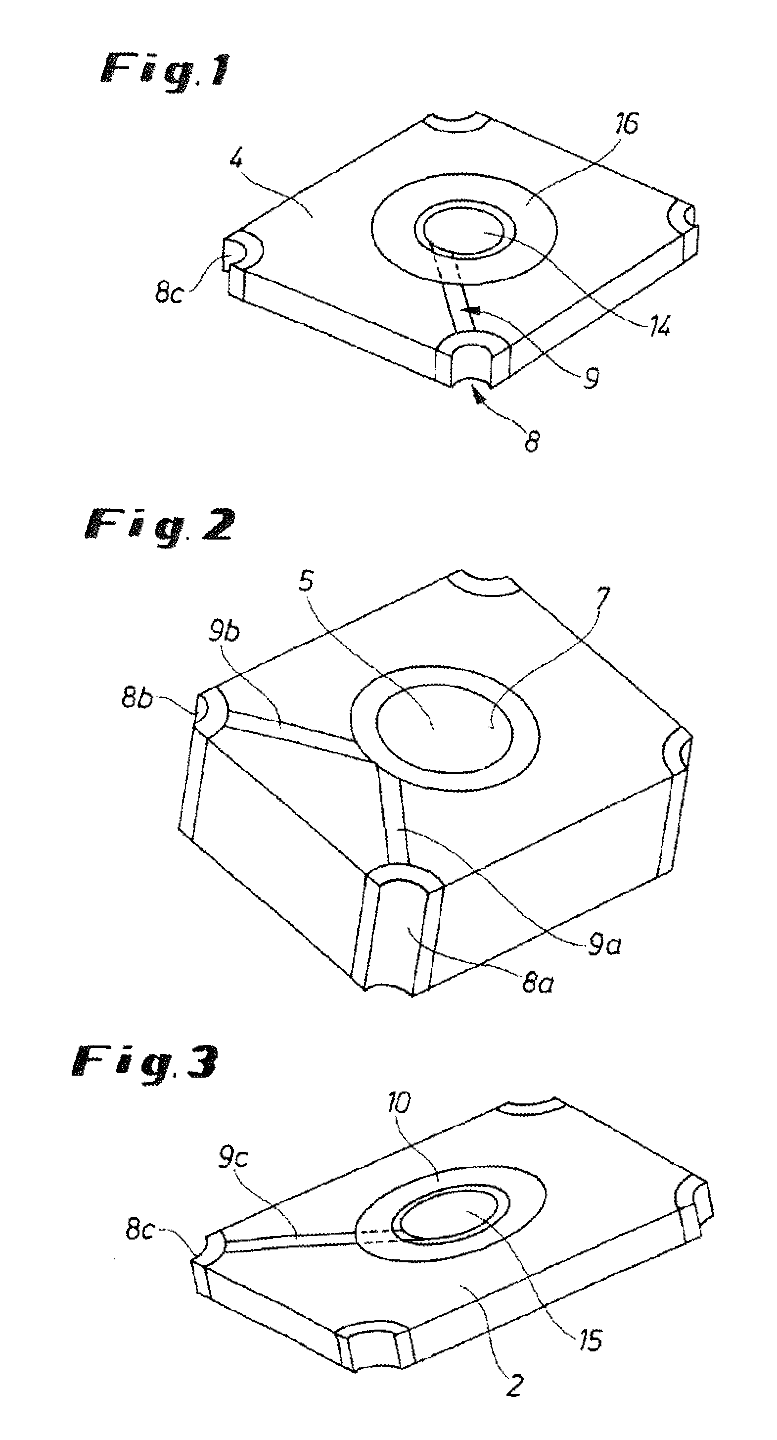
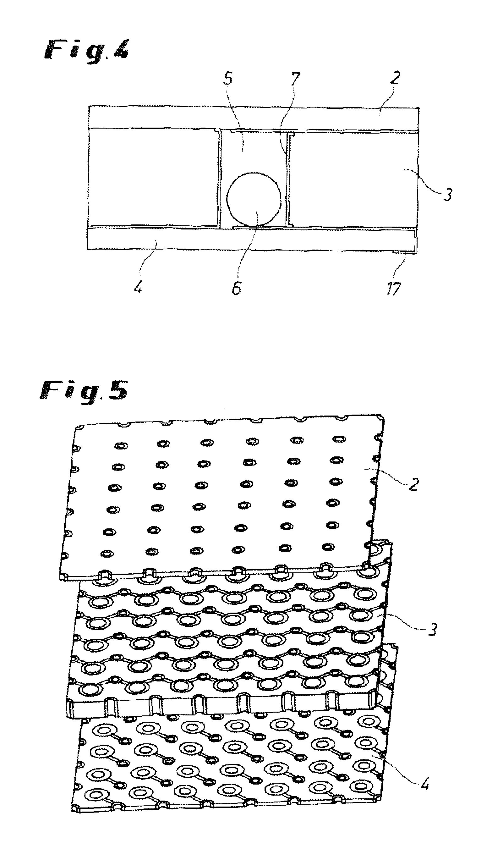
[0086]The element illustrated in FIG. 1 is the base plate 4. The contact surface 14 is arranged centrally. An electrical connection leads from said contact surface via the conductor tracks 9 to a connection contact 8. The latter is arranged at a corner point of the base plate and configured in a virtually circular fashion.

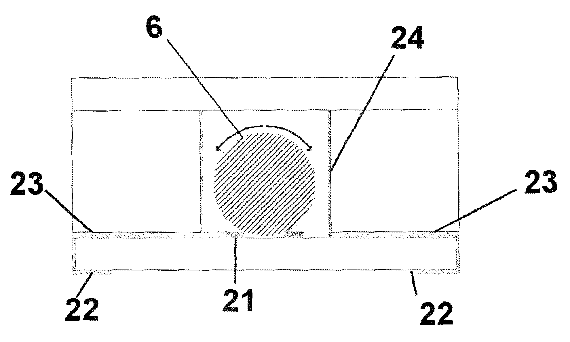
[0087]FIG. 2 illustrates the chamber plate 3. A drilled hole for producing the cavity 5 can be discerned in the center. The inner walls 7 of said drilled hole form the inner surfaces the electrically conductive inner surfaces of the cavity 5. Conductor tracks (in Example 2 conductor tracks), lead from the electrically conductive inner surfaces 7 to two connection contacts 8. Electrically conductive connections to the connection contact of the base plate 4 are involved. The conductor track 9a is accordingly aligned in a manner corresponding to the conductor track 9 of the base plate 4.

[0088]FIG. 3 illustrates the cover plate 2. The latter is aligned mirror-symmetric...


PUM


Abstract

The present invention relates to a movement sensor that comprises a plurality of plate-type layers on which individual sensors are arranged. The layers are configured in the way set forth in the claims.

Description

BACKGROUND OF THE INVENTION[0001]1. Field of the Invention[0002]The present invention relates to a movement sensor and to the use thereof for position and movement detection.[0003]2. Discussion of Background Information[0004]Movement sensors have been known for decades. They primarily serve the purpose of detecting simple movements. They exist in different variants, with all of them having in common the fact that they contain a conductive ball or a drop of mercury. Such apparatuses are known e.g. from U.S. Pat. No. 3,927,286 and U.S. Pat. No. 4,434,337.[0005]U.S. Pat. No. 5,410,113 A discloses a movement sensor comprising a plurality of plate-type layers on which individual sensors are arranged. The cover plate and the base plate each have a sensor-associated surface, which are connected to connection contacts via conductor tracks. A chamber plate having a cutout is arranged between the cover plate and the base plate. The sensor-associated surfaces of the cover plate and of the base...

Claims


Application Information

Patent Timeline
Patent Type & Authority Patents(United States)
IPC IPC(8): G01R27/08G01B11/14H01H1/16H01H35/02H01H35/14
CPCG01B11/14H01H1/16H01H35/02H01H35/142
Inventor BLANK, THOMASHAGER, MARCOHUBER, DOMINIC
Owner KARLSRUHER INST FUR TECH
Why Eureka
Try Eureka