Transflective liquid crystal display device

a liquid crystal display and reflection type technology, applied in non-linear optics, instruments, optics, etc., can solve the problems of deterioration of visibility of reflection type lcd devices in dark surroundings, often insufficient panel brightness, etc., and achieve the effect of minimizing possible domain defects (non-transferred splay-aligned regions)

Inactive Publication Date: 2010-06-01
WINTEK CORP
View PDF16 Cites 2 Cited by
  • Summary
  • Abstract
  • Description
  • Claims
  • Application Information

AI Technical Summary

Benefits of technology

[0011]Hence, an object of the invention is to provide an optically compensated birefringence (OCB) mode transflective liquid crystal display device that operates at a low threshold voltage to realize a wide view-field angle and high-speed response and possesses good visibility in any environment.
[0013]Through the design of the invention, since the reflective electrode and the transparent electrode are spaced apart from each other, a traverse electric field applied in different horizontal directions is produced when a voltage difference exists between the two separate electrodes. Hence, in case of having splay alignment of liquid crystal molecules under the initial state of an OCB mode, the liquid crystal molecules will tilt toward different directions following the different horizontal directions of the traverse electric field to result in azimuthal disorder of tilt angle directions. Under the circumstance, it is easy to create a great number of transition nucleuses that contribute to transform the splay alignment into the bend alignment due to the azimuthal disorder of tilt angle directions. Thereby, the OCB cell is quickly transformed into a bend-aligned state to effect a display device, and possible domain defects (non-transferred splay-aligned regions) are minimized as a result.

Problems solved by technology

Though the transmission type LCD device uses backlight to obtain a bright display independent of surrounding environments, the panel brightness is often not sufficient when the device is exposed to direct sunlight.
In comparison, a reflection type LCD device employs surrounding light to effect a display so that a backlight source is omitted; however, the reflection type LCD device is largely deteriorated in visibility in a dark surrounding.

Method used


Image

  • Transflective liquid crystal display device
  • Transflective liquid crystal display device
  • Transflective liquid crystal display device

Examples


Embodiment Construction

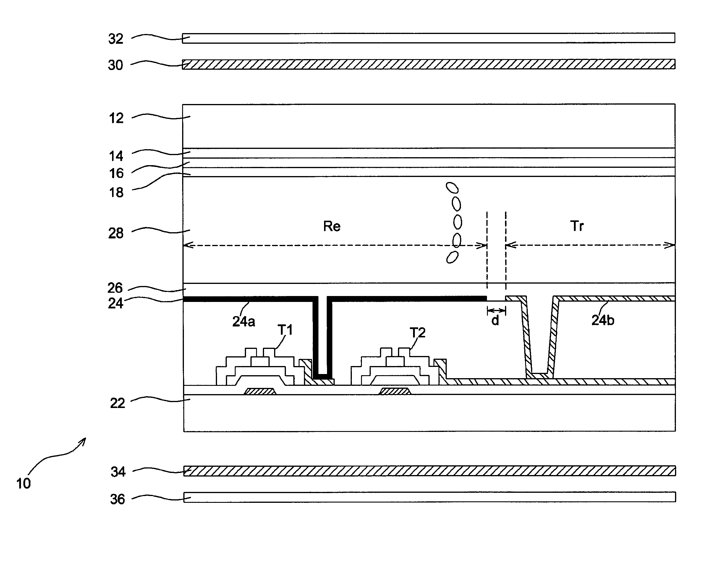
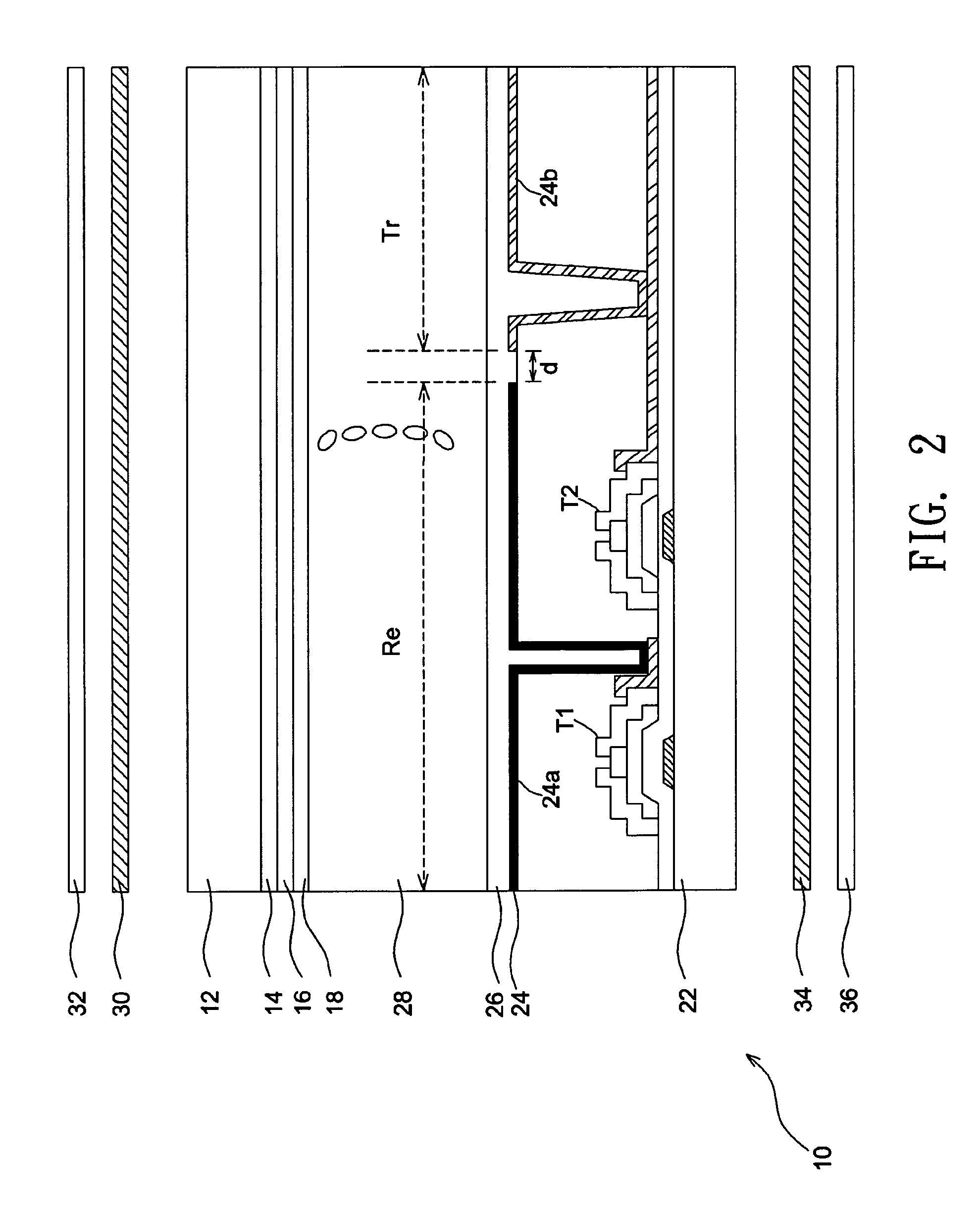
[0027]FIG. 2 shows a sectional schematic view illustrating a transflective liquid crystal display (LCD) device 10 according to an embodiment of the invention. Though the transflective LCD device 10 includes a plurality of picture elements, FIG. 2 simply illustrates one of them since all the picture elements have identical structures.

[0028]Referring to FIG. 2, a first substrate 12 and a second substrate 22 are placed to face with each other, and a liquid crystal layer 28 functioning in an optically compensated birefringence (OCB) mode is interposed between them. On the first substrate 12 a color filter 14, a common electrode 16, and a first alignment film 18 are sequentially formed. The common electrode 16 is formed from indium tin oxide (ITO) or indium zinc oxide (IZO) transparent conductive films. On the second substrate 22 a pixel electrode 24 and a second alignment film 26 are formed. Further, a first biaxial film 30 and a first polarizer 32 are positioned in one side of the firs...


PUM

PropertyMeasurementUnit
angleaaaaaaaaaa
twist angleaaaaaaaaaa
birefringenceaaaaaaaaaa

Abstract

A transflective liquid crystal display device includes a first and a second substrates, a liquid crystal layer, and a plurality of reflective electrodes and transparent electrodes. The liquid crystal layer is interposed between the first and the second substrates and functions in an OCB mode. The reflective electrode and the transparent electrode in one picture element are spaced apart from each other to produce a transverse electric field when a voltage is applied across the liquid crystal layer.

Description

BACKGROUND OF THE INVENTION[0001](a) Field of the Invention[0002]The invention relates to a transflective liquid crystal display device and, more particularly, to a transflective liquid crystal display device using an OCB (optically compensated birefringence) technique which realizes a wide view-field angle and high-speed response.[0003](b) Description of the Related Art[0004]Twisted nematic (TN) cells, which at present are widely used in thin film transistor (TFT) liquid crystal display devices, have a small view-field angle and low-speed respond. To solve this problem, studies on an OCB (optically compensated birefringence) technique have been made. Specifically, in case of displaying moving images, a response time is required in the order of ten milliseconds or even less, and the OCB technique is possible to obtain a high-speed response characteristic as well as a wide view-field angle. Hence, it is the best mode suitable for accommodating a recent trend of multimedia and motion ...

Claims


Application Information

Patent Timeline
Patent Type & Authority Patents(United States)
IPC IPC(8): G02F1/1335
CPCG02F1/133555G02F1/133707G02F1/1395
Inventor WU, YI-CHUNLIAO, WEN-JUILIU, CHIN-CHANGLEE, CHIAN-CHANG
Owner WINTEK CORP
Why Eureka
Try Eureka