Hydraulic workholding assembly

Inactive Publication Date: 2007-04-26
MFR & TRADERS TRUST COMPANY AS AGENT
View PDF26 Cites 11 Cited by
  • Summary
  • Abstract
  • Description
  • Claims
  • Application Information

AI Technical Summary

Benefits of technology

[0007] Accordingly, one aspect of one or more embodiments of this invention provides an improved hydraulic workholding assembly.
[0008] Another aspect of one or more embodiments of this invention provides a hydraulic pressure generator for use with a hydraulic collet, wherein the generator relies on a mechanical connection to a draw bar to provide the hydraulic pressure. The mechanical connection eliminates the need for a separate hydraulic power supply or hydraulic passages that extend from an underlying machine into the hydraulic workholding assembly.

Problems solved by technology

Unfortunately, conventional hydraulic collet assemblies required complex centering mechanisms (e.g., additional centering pistons) to center the work pieces before gripping them.

Method used


Image

  • Hydraulic workholding assembly
  • Hydraulic workholding assembly
  • Hydraulic workholding assembly

Examples


Embodiment Construction

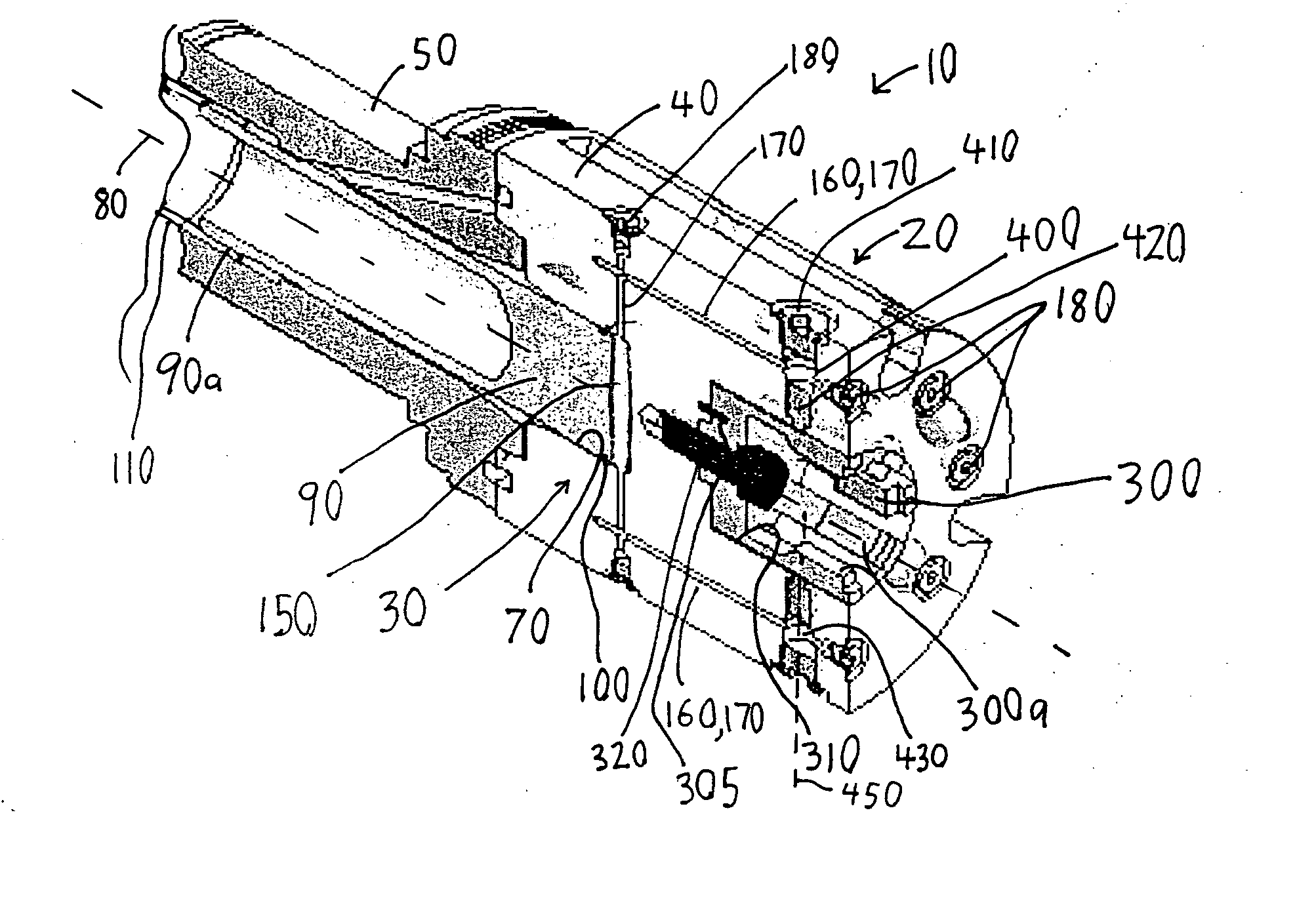
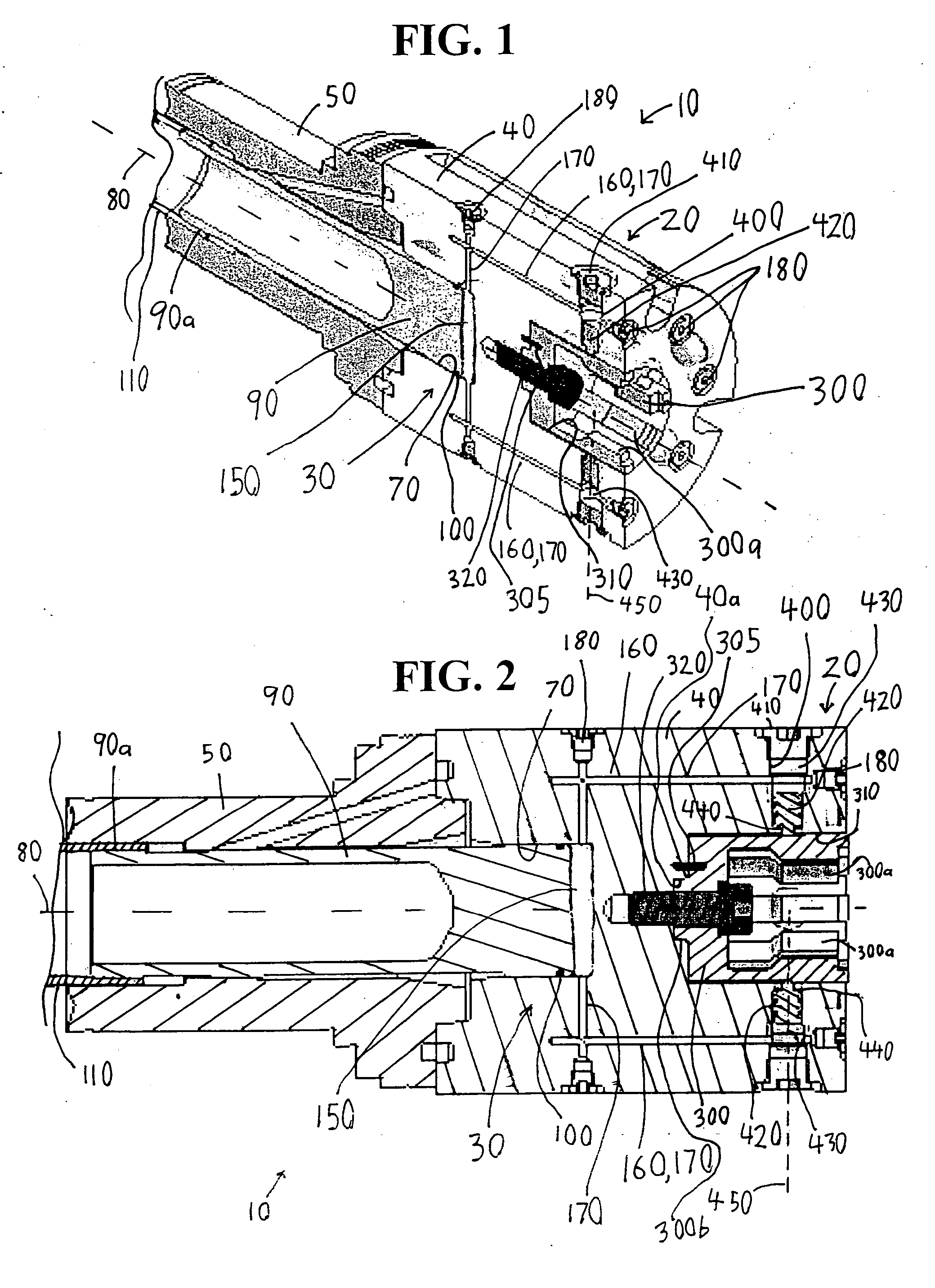
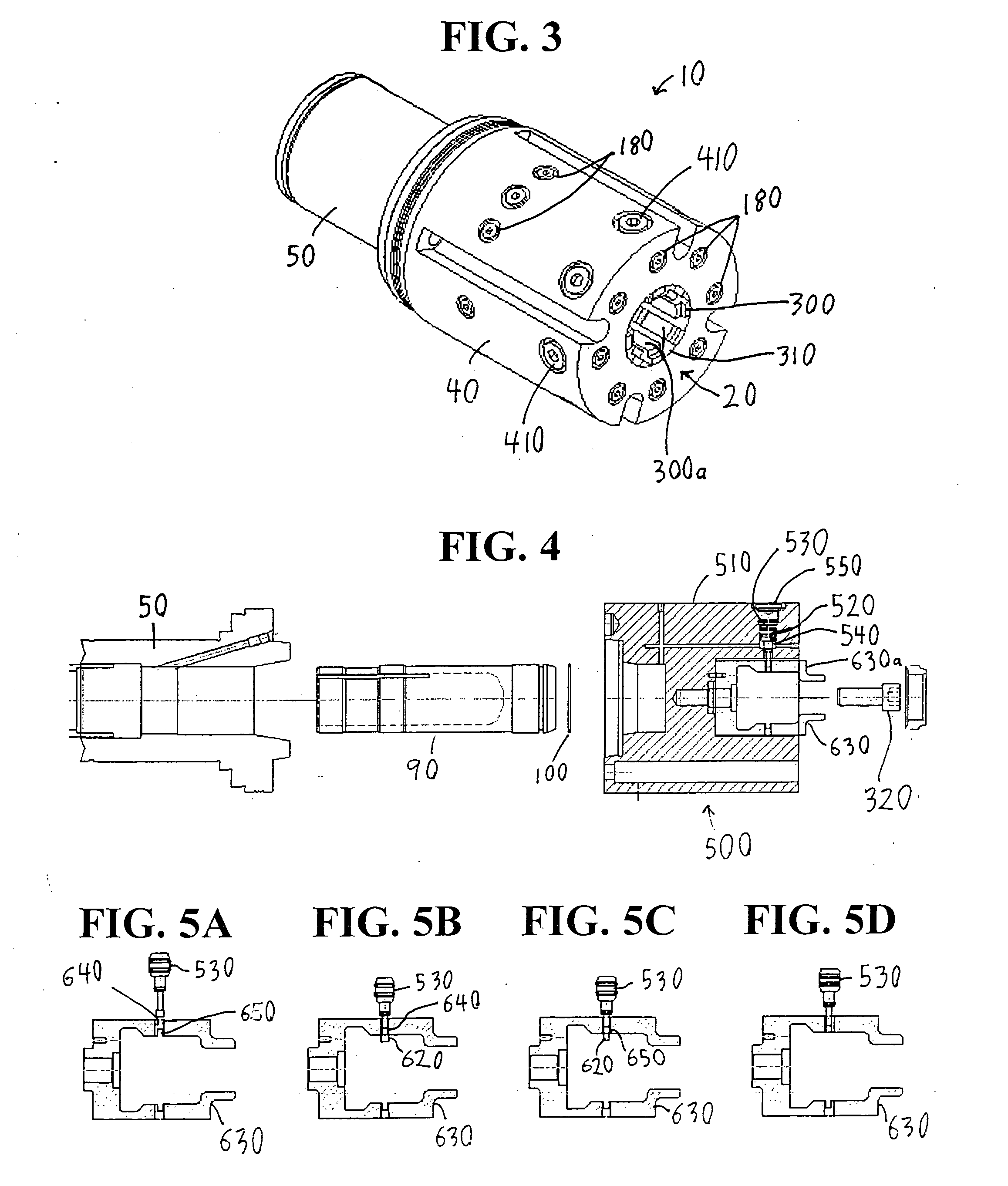
[0040]FIGS. 1-3 illustrate a hydraulic workholding assembly 10 according to an embodiment of the present invention. The assembly 10 includes a hydraulic collet assembly 20 that is operated via a hydraulic pressure generator 30.

[0041] Hereinafter, the hydraulic pressure generator 30 is described with reference to FIGS. 1, 2, and 6. As shown in FIG. 1, the assembly 10 includes a housing 40 that securely mounts to a spindle 50 of an underlying machine 60 (see FIG. 6). As shown in FIGS. 1-2, a hydraulic cylinder 70 is formed in the housing 40 and is concentric with an axis 80 of the spindle 50.

[0042] As shown in FIGS. 1 and 2, a piston 90 slidably extends through a bore in the spindle 50 and into the cylinder 70. A sealing O-ring 100 extends around the outer circumferential surface of the piston 90 to create a sealed connection between the piston 90 and cylinder 70. A rearward portion 90a of the piston 90 is externally threaded and threadingly engages an internally threaded portion 11...


PUM


Abstract

A workholding assembly for releasably holding a work piece includes a master variable-volume fluid chamber disposed between a machine and the machine's axially-movable draw bar such that the workholding assembly converts the mechanical axial force / movement of the draw bar into fluid pressure / fluid flow. The resulting fluid pressure operates a fluid-driven gripping assembly such as a radial-piston-based hydraulic collet assembly or a diaphragm-based hydraulic gripping assembly. The hydraulic collet assembly may be a quick-change assembly that enables an operator to quickly and easily change between differently sized or shaped collets.

Description

BACKGROUND OF THE INVENTION [0001] 1. Field of the Invention [0002] This invention relates to the use of hydraulic pressure to grip a work piece within a workholding assembly. [0003] 2. Description of Related Art [0004] A conventional workholding assembly typically includes a gripping assembly (e.g., a collet assembly or chuck assembly) that uses gripping jaws that synchronously move radially inward and outward equal distances. If such a conventional gripping assembly grips the outside diameter of an out-of-round work piece, the gripping assembly will tend to deform the work piece into a round shape because the gripping jaw that abuts a portion of the work piece with a larger diameter will apply a greater force to that portion of the work piece. The deformed work piece, such as a bearing race, is machined round while in its deformed shape, but elastically rebounds into an out-of-round position when released from a conventional gripping assembly. [0005] As shown in U.S. Pat. No. 6,12...

Claims


Application Information

Patent Timeline
IPC IPC(8): B23B31/30
CPCB23B31/16287B23B31/205Y10T279/1291B23B2260/034B23B31/32B23B31/207
Inventor SOROKA, DANIEL P.DESRUISSEAUX, NEALCOLVIN, JOSEPH
Owner MFR & TRADERS TRUST COMPANY AS AGENT
Why Eureka
Try Eureka