Pulsed power supply with current ripple reduction

a technology of current ripple and power supply, which is applied in the direction of pulse generator, pulse train generator, pulse technique, etc., can solve the problems of large amount of current drawn, large cost of passive filter elements required to filter low frequency current ripple, and modulation in the typical power supply

Active Publication Date: 2007-04-26
HAMILTON SUNDSTRAND CORP
View PDF14 Cites 12 Cited by
  • Summary
  • Abstract
  • Description
  • Claims
  • Application Information

AI Technical Summary

Problems solved by technology

The amount of energy required by the pulsed thruster results in a large amount of current being drawn from the typical power supply to the pulsed load power supply.
However, in applications in which the pulsed load is fired at a relatively slow frequency (e.g., 50 Hz), the passive filter eleme

Method used


Image

  • Pulsed power supply with current ripple reduction
  • Pulsed power supply with current ripple reduction
  • Pulsed power supply with current ripple reduction

Examples


Embodiment Construction

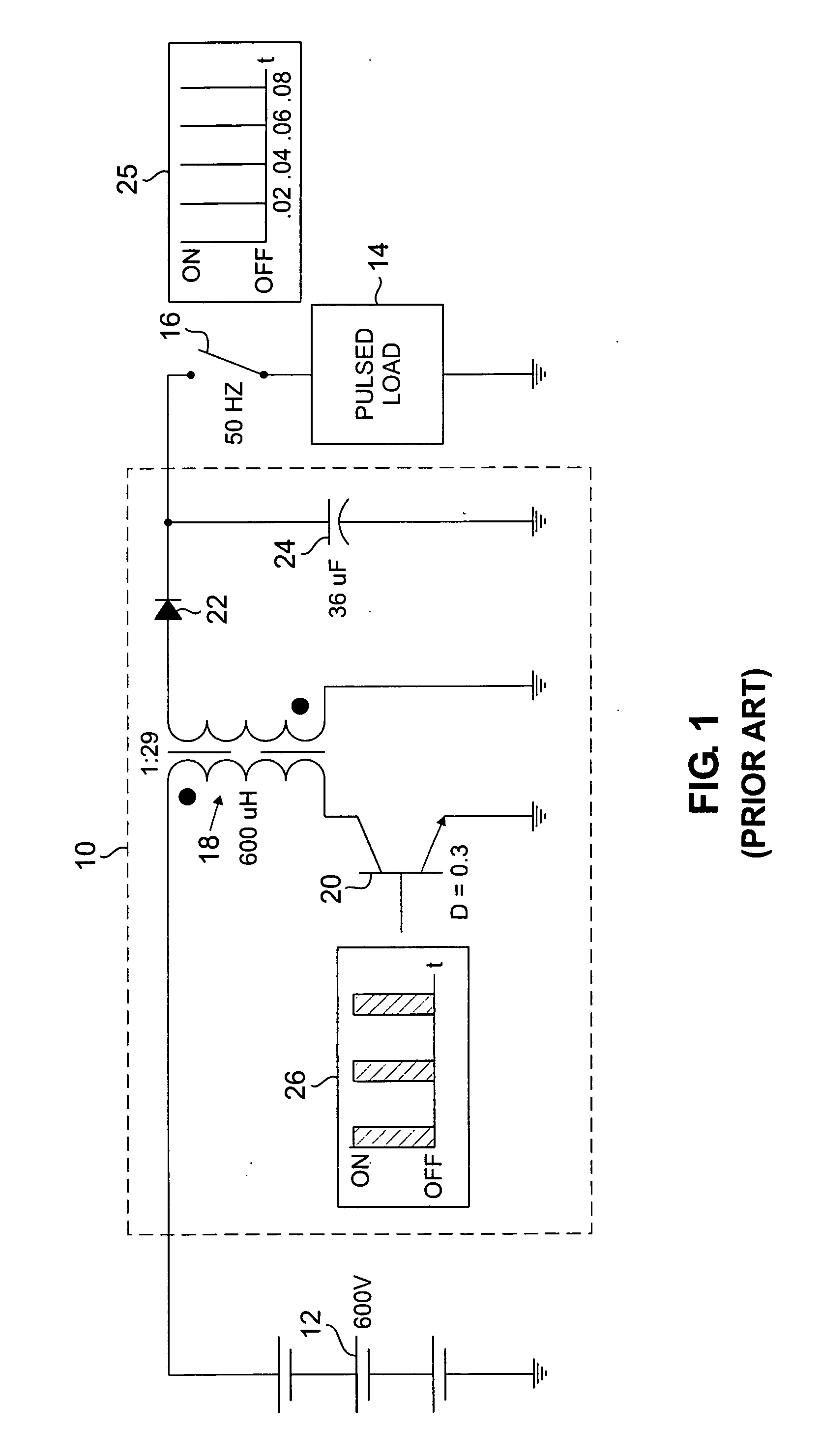
[0010]FIG. 1 shows a typical pulsed load power supply 10 connected to receive charging power from main power supply 12, and to provide pulsed power to pulsed load 14 through switch 16. Pulsed load power supply circuit 10 includes transformer 18, transistor 20, diode 22, and capacitor 24. Pulsed load power supply circuit 10 is connected in a simple “flyback” configuration to provide a large charging voltage to capacitor 24. After pulsed load power supply circuit 10 charges capacitor 24 to a sufficient level, switch 16 is closed, allowing capacitor 24 to discharge through pulsed load 14. Graph 26 illustrates an exemplary embodiment of a pulse pattern applied to selectively open and close switch 16 at a rate of 50 Hertz (Hz). As shown in graph 26, switch 16 is only closed for a short amount of time, allowing a pulse of energy to be supplied to pulsed load 14.

[0011] The flyback circuit configuration operates by switching transistor 20 between a conducting and a non-conducting state at ...


PUM


Abstract

A pulsed power source minimizes current ripple disturbance in a main power supply by dividing the pulsed load into a plurality of pulsed sub-loads. The pulsed power source includes a plurality of pulsed load power supplies, each pulsed load power supply receiving charging power from the main power supply and providing pulsed energy to one of the plurality of pulsed sub-loads. Pulsed energy delivered to each of the plurality of pulsed sub-loads is out of phase with the other pulsed sub-loads, resulting in the input current provided by the main power supply having a reduced current ripple magnitude and increased current ripple frequency.

Description

BACKGROUND OF THE INVENTION [0001] A number of applications require the delivery of high-energy pulses. These types of applications are known generally as pulsed loads. Applications that make use of pulsed power include radar, lasers, rail guns, and pulsed thrusters for space propulsion. In order to generate the high-energy pulse necessary to drive the pulsed load, a typical power supply (e.g., a dc power source) is connected to provide charging power to a pulsed load power supply. The pulsed load power supply stores energy provided by the typical power supply in a large storage device, such as a capacitor. When a pulse of energy is required by the pulsed load, a switch connecting the capacitor to the pulsed load is closed, allowing energy stored in the capacitor to be supplied to the pulsed load. [0002] Oftentimes, applications employing pulsed loads require the “firing” or discharge of energy through the pulsed load at a regular interval or frequency. An example of one such applic...

Claims


Application Information

Patent Timeline
IPC IPC(8): H02J3/00
CPCH02M1/14H02M3/285H02M2001/008H02M1/008
Inventor FOX, DAVID ALAN
Owner HAMILTON SUNDSTRAND CORP
Why Eureka
Try Eureka