Wire rope flaw detector for elevator

Inactive Publication Date: 2007-04-26
TOSHIBA ELEVATOR KK
View PDF7 Cites 20 Cited by
  • Summary
  • Abstract
  • Description
  • Claims
  • Application Information

AI Technical Summary

Benefits of technology

[0014] The present invention is made in view of the above problems. An object of the present invention is to provide a flaw detection apparatus for a wire rope of an elevator, that can provide an enhanced maintenance workability when used in a space- and energy-saving elevator having a wire rope of a smaller diameter.
[0026] According to the present invention, in an elevator having a wire rope of a small diameter having a nominal diameter of 4 mm to 8 mm, a flaw of the wire rope can be detected in a highly reliable manner with a minimum space. A time required for detecting a flaw can be drastically reduced in an elevator having an increased number of wire ropes. Accordingly, a time period when the elevator is stopped for a maintenance can be shortened, which in turn elongates a time period when the elevator is in service. In addition, especially in a machineroom-less elevator, the flaw detection apparatus according to the present invention makes it possible for an operator to gather signals outside an elevator shaft whereby an improved safety is provided.

Problems solved by technology

However, such visual observation is not easy because of the thin wires.
As a result, a longer time is required for a maintenance operation, especially for a flaw detection operation and a strength determination operation.
In the above-described flaw detection apparatus utilizing a leakage flux, the leakage flux at a flaw portion is generally reduced because of the thinner wires, which leads to a deterioration of a flaw detection sensibility of the leakage flux.
Although these inconveniences may largely be dependent on positions and sizes of the rope and the magnetic sensors, such disadvantages are inconsistent with the desired aspects of the elevator in terms of an achievement of space-saving elevator equipments and an improvement of a flaw detection performance.

Method used


Image

  • Wire rope flaw detector for elevator
  • Wire rope flaw detector for elevator
  • Wire rope flaw detector for elevator

Examples


Embodiment Construction

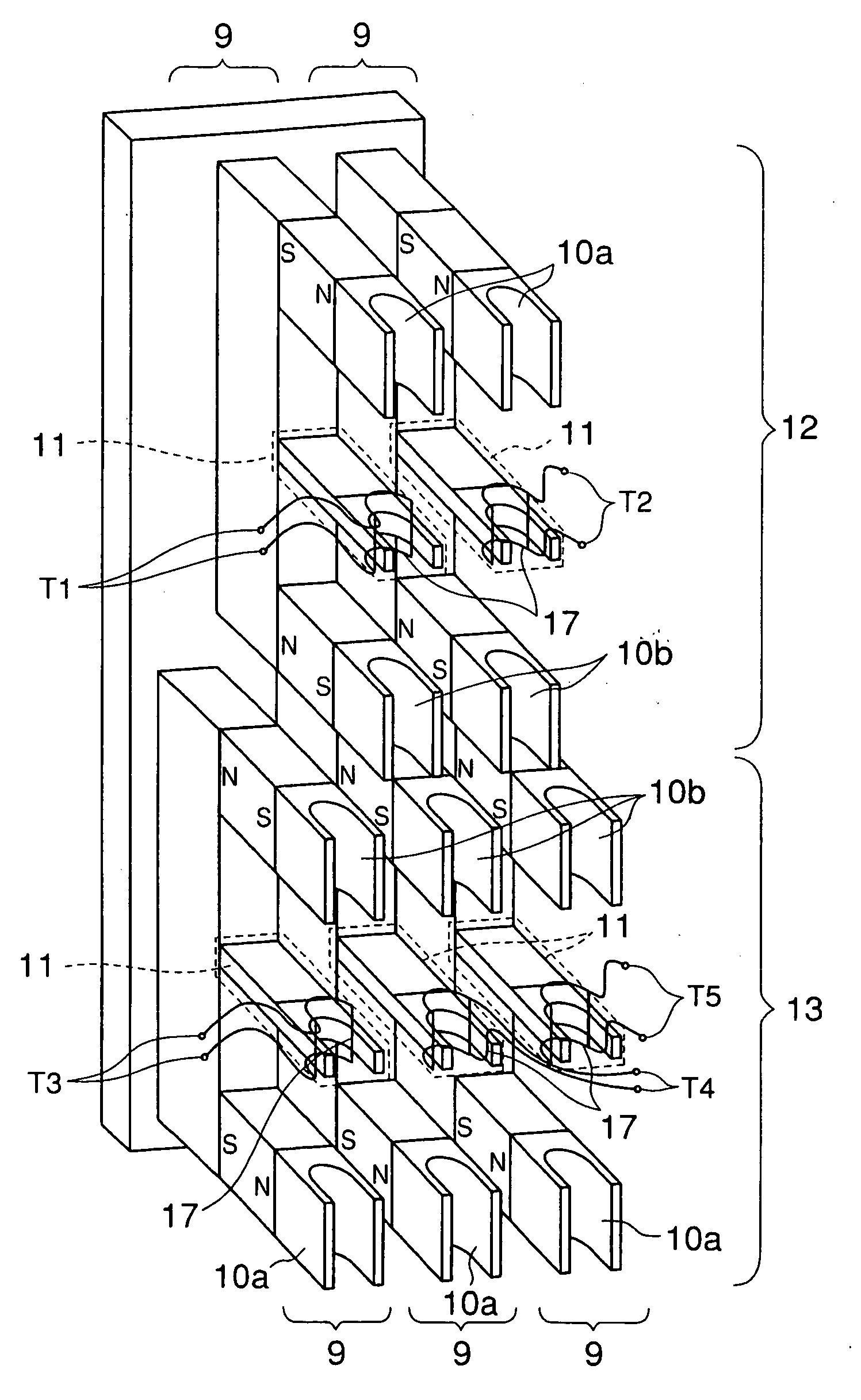
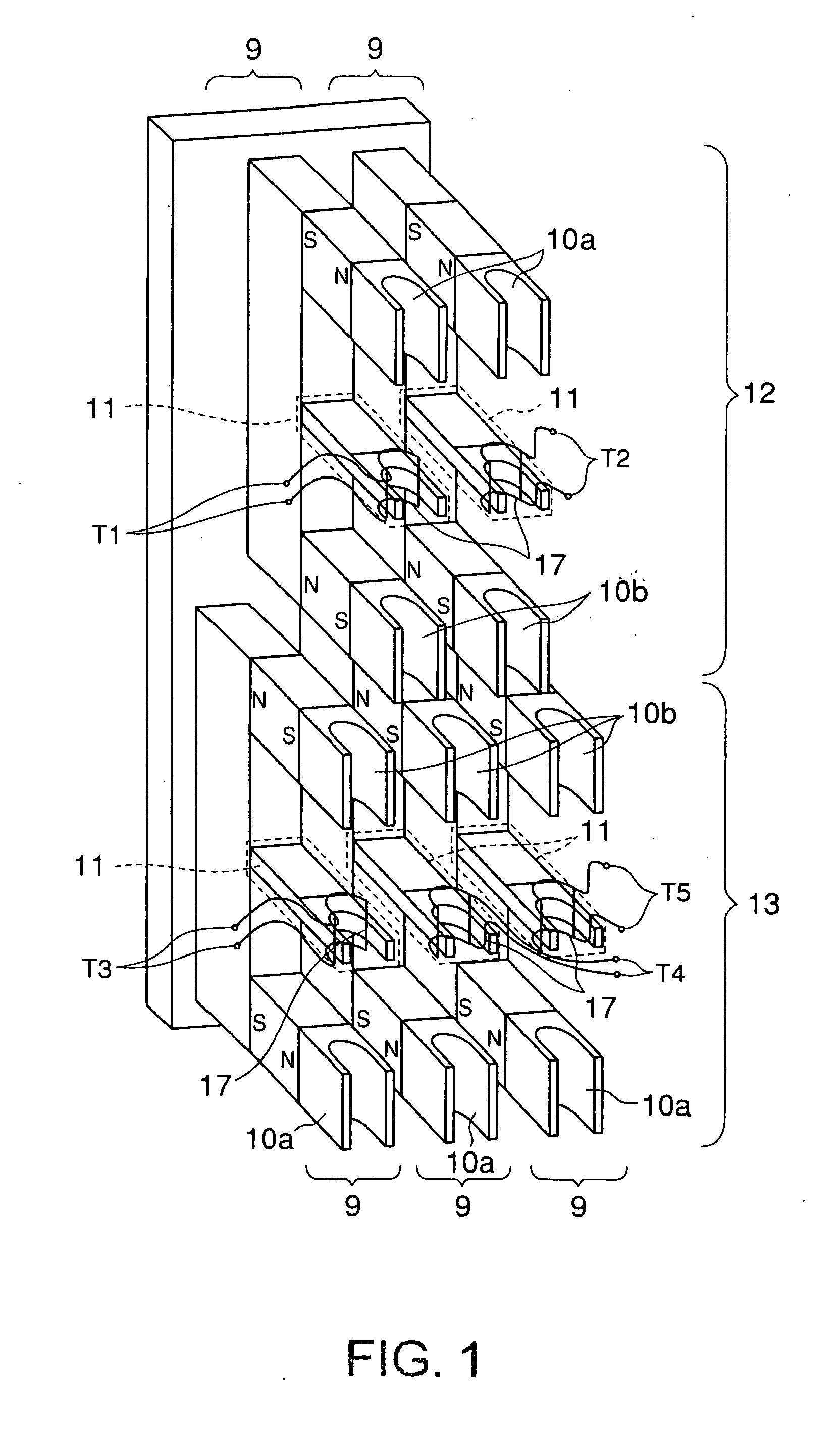
[0035] An embodiment of the present invention will be described below with reference to the drawings. FIGS. 1 to 6 are views showing an embodiment of the flaw detection apparatus for a wire rope of an elevator according to the present invention.

[0036] The flaw detection apparatus for a wire rope of an elevator according to the present invention can be applied to an elevator using a wire rope of a smaller diameter so as to save space and energy. A nominal diameter of the rope is in a range of 4 mm to 8 mm.

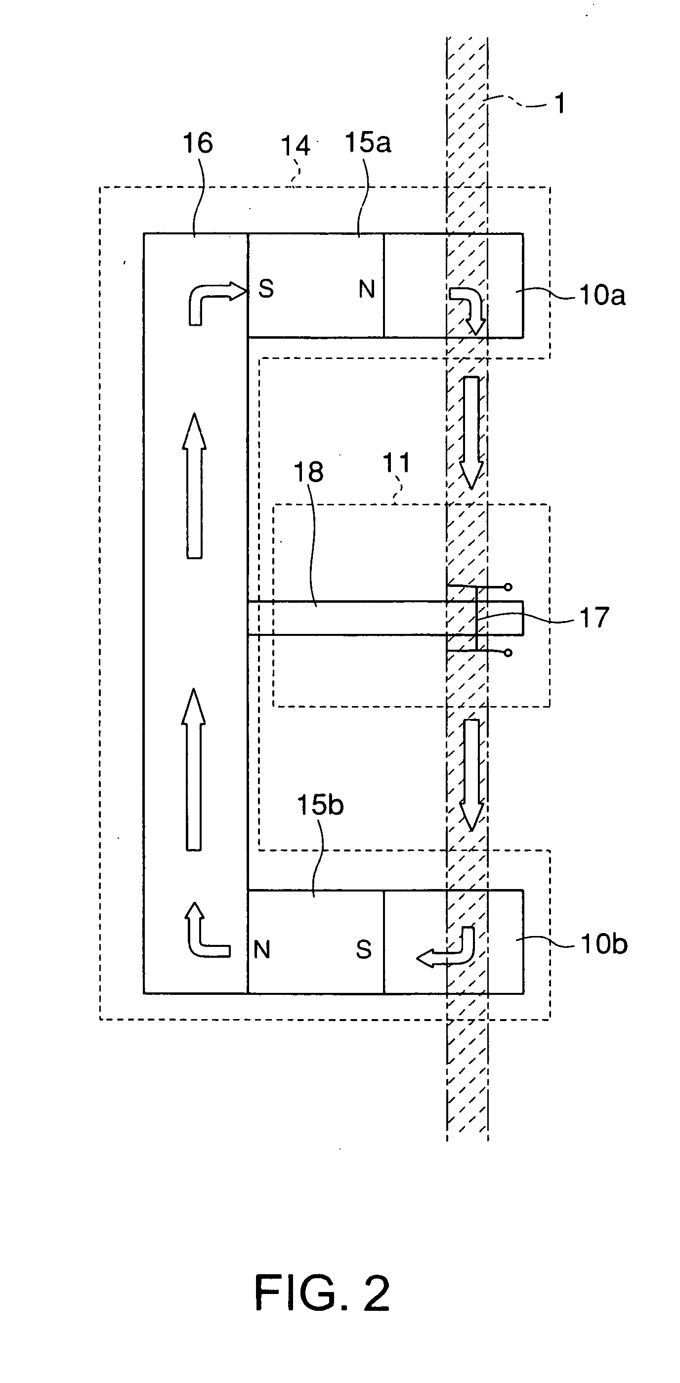
[0037] As shown in FIGS. 1 to 3, the flaw detection apparatus for a wire rope of an elevator includes a plurality of flaw detectors (unit probes) 9. Each of the flaw detectors (unit probes) 9 has a first and a second magnetic poles 10a and 10b of different polarity, and a magnetic sensor 11 of a U-shape disposed between the first magnetic pole 10a and the second magnetic pole 10b. The first magnetic pole 10a is a north pole, while the second magnetic pole 10b is a south pole.

[003...


PUM


Abstract

A flaw detection apparatus for a wire rope of an elevator according to the present invention, which is intended for a wire rope having a nominal diameter of 4 mm to 8 mm, includes a plurality of unit probes 9. Each of the unit probes 9 has a first and a second magnetic poles 10a and 10b of different polarity, and a magnetic sensor 11 of a U-shape disposed between the first magnetic pole 10a and the second magnetic pole 10b. A bottom radius of the magnetic sensor 11 is in a range of 2 mm to 5 mm. A difference between the bottom radius of the magnetic sensor 11 and a half of the nominal diameter of a wire rope 1 is equal to or less than 1.5 mm.

Description

BACKGROUND OF THE INVENTION [0001] 1. Field of the Invention [0002] The present invention relates to a flaw detection apparatus for a wire rope of an elevator, which is used for the maintenance of a wire rope suspending an elevator car of an elevator. [0003] 2. Background Art [0004] A wire rope supporting an elevator car of an elevator must be maintained in accordance with regulations and repaired as needed. In general, breaking and abrasion of wires is checked for by visually observing the wires to determine a remaining strength of the wire rope. However, such visual observation is not easy because of the thin wires. Thus, a magnetic flaw detection apparatus shown in FIG. 7 has conventionally been used for more rapidly detecting a flaw in wires, such as breaking, abrasion, kinks, and so on. [0005] In FIG. 7, the reference numbers 1 and 2 show a rope to be measured and a flaw detector (hereinafter referred to as a “probe”) of the magnetic flaw detection apparatus, respectively. The ...

Claims


Application Information

Patent Timeline
IPC IPC(8): G01N27/82B66B5/12B66B7/12G01N27/83
CPCB66B5/125G01N27/83B66B7/123
Inventor OSADA, AKIRAOKAMOTO, MASAKATSU
Owner TOSHIBA ELEVATOR KK
Why Eureka
Try Eureka