Method and apparatus for adjusting the pressure sensor measurement range in a tire pressure monitoring system

a technology of pressure sensor and monitoring system, which is applied in the direction of inflated body pressure measurement, instruments, machines/engines, etc., can solve the problems of increasing the overall cost to the manufacturer, and achieve the effect of increasing the resolution of the pressure sensor, and reducing the overall cost of the system

Active Publication Date: 2007-04-26
FORD GLOBAL TECH LLC
View PDF99 Cites 25 Cited by
  • Summary
  • Abstract
  • Description
  • Claims
  • Application Information

AI Technical Summary

Benefits of technology

[0008] One advantage of the invention is that the pressure sensors may be commonized for a manufacturer. This reduces the overall cost of the system by commonizing components.
[0009] Another advantage of the system is that the range may be tailored to a smaller range and thus the resolution of the pressure sensors may be increased. Increasing the resolution of the sensors increases the amount of data and decreases false warnings.
[0010] Other advantages and features of the present invention will become apparent when viewed in light of the detailed description of the preferred embodiment when taken in conjunction with the attached drawings and appended claims.

Problems solved by technology

However, requiring different pressure sensors increases the overall cost to the manufacturer.

Method used


Image

  • Method and apparatus for adjusting the pressure sensor measurement range in a tire pressure monitoring system
  • Method and apparatus for adjusting the pressure sensor measurement range in a tire pressure monitoring system
  • Method and apparatus for adjusting the pressure sensor measurement range in a tire pressure monitoring system

Examples


Embodiment Construction

[0018] In the following figures, the same reference numerals will be used to illustrate the same components. Those skilled in the art will recognize that the various components set forth herein could be changed without varying from the scope of the invention.

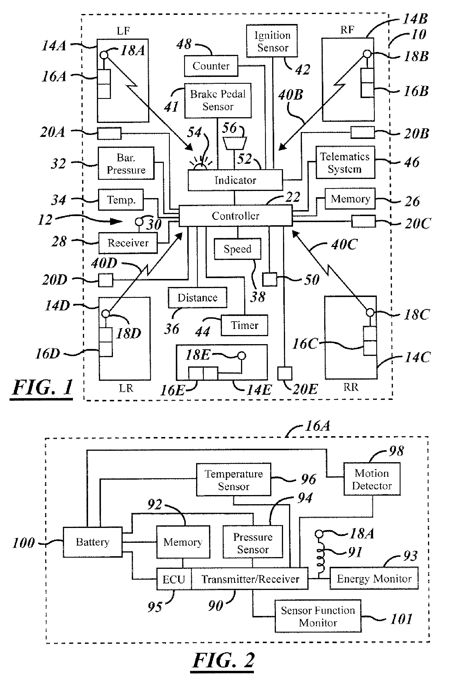
[0019] Referring now to FIG. 1, an automotive vehicle 10 has a pressure monitoring system 12 for monitoring the air pressure within a left front tire 14a, a right front tire 14b, a right rear tire 14c, and a left rear tire 14d. Each tire 14a-14d has a respective tire pressure sensor circuit 16a, 16b, 16c, and 16d, each of which has a respective antenna 18a, 18b, 18c, and 18d. Each tire is positioned upon a corresponding wheel.

[0020] A fifth tire or spare tire 14e is also illustrated having a tire pressure sensor circuit 16e and a respective antenna 18e. Although five wheels are illustrated, the pressure of various numbers of wheels may be increased. For example, the present invention applies equally to vehicles such as pickup ...


PUM


Abstract

A tire pressure monitoring system (12) for a vehicle (10) has a pressure sensor circuit (16A) that includes an ECU (95), a transmitter/receiver (90), and pressure sensor (94). A method of operating a tire pressure monitoring system includes calibrating a tire pressure sensor circuit in a first range and a second range and generating a first calibration data for the first range and second calibration data for the second range. The first calibration data and the second calibration data are stored in a memory of the tire pressure sensing circuit (16A). A data signal corresponding to the pressure is generated. The first or second calibration data is generated in response to the range of the data signal to form a selected calibration. The data signal is calibrated with the selected calibration to form a pressure indicative signal. The pressure indicative signal is transmitted to a receiver (28) within the vehicle (10) with a range status corresponding to the selected calibration. A pressure signal is formed in response to the pressure indicative signal and the range status and the tire pressure monitoring system is operated with the pressure signal.

Description

TECHNICAL FIELD [0001] The present invention relates generally to a tire pressure monitoring system for an automotive vehicle, and more particularly, to a method and system for adjusting the pressure sensor range. BACKGROUND OF THE INVENTION [0002] Various types of pressure sensing systems for monitoring the pressure within the tires of an automotive vehicle have been proposed. Such systems generate a pressure signal using an electromagnetic (EM) signal which is transmitted to a receiver. The pressure signal corresponds to the pressure within the tire. When the tire pressure drops below a predetermined pressure, an indicator is used to signal the vehicle operator of the low pressure. Many vehicles require different tire pressures in the front of the vehicle and the rear of the vehicle. Therefore, it is important to know the relative position of the pressure sensor and thus the tires relative to the vehicle. [0003] The National Highway Traffic Safety Administration is requiring a pha...

Claims


Application Information

Patent Timeline
Patent Type & Authority Applications(United States)
IPC IPC(8): B60C23/00G01F23/00
CPCB60C23/0408B60C23/0474B60C23/0415G01D3/024G01L17/00
Inventor MILLER, THOMASMCQUADE, THOMASSWADLING, GREGWOJCIK, KARL
Owner FORD GLOBAL TECH LLC
Why Eureka
Try Eureka