
Liquid Cooled Mirror for Use in Extreme Ultraviolet Lithography

a liquid-cooled mirror and ultraviolet lithography technology, applied in photomechanical equipment, instruments, nuclear engineering, etc., can solve the problems of degrading affecting the optical performance of the mirror, and often insufficient radiant cooling methods for cooling the mirror

Active Publication Date: 2007-04-26
NIKON CORP
View PDF4 Cites 51 Cited by
  • Summary
  • Abstract
  • Description
  • Claims
  • Application Information

AI Technical Summary

Benefits of technology

[0011] In one embodiment, the microchannel is part of an azimuthal array of radial microchannels having a pressure drop within the microchannel, when the fluid is contained within the microchannel is less than approximately twenty kiloPascal (kPa).
[0012] When a liquid-cooled mirror that may be used in a EUV lithography system uses a liquid with laminar flow properties, vibrat

Problems solved by technology

Heat generally causes distortion in the mirror, thereby degrading the optical performance of the mirror.
When there is distortion in the mirror, the optical performance of the mirror is compromised.
Although radiant cooling methods may be effective in cooling mirrors while causing an insignificant amount of distortion, when the heat load on a mirror is relatively high, radiant cooling methods are often inadequate for cooling mirrors.
However, the use of turbulent or non-laminar flow to cool a mirror generally causes the mirror to vibrate.
When a mirror that is cooled by internal cooling methods which utilize turbulent flow is a part of a EUV lithography system, the vibrations caused by the turbulent flow may adversely affect a lithography process, particularly if the vibrations cause an illuminator unit, projection optics, a reticle, or a wafer to vibrate.
As a result, the accuracy of the EUV lithography process may be compromised.
The radiating of heat to structures in a EUV lithography apparatus may cause adverse structural changes and, as a result, adversely affect the performance of the structures.

Method used


Image

  • Liquid Cooled Mirror for Use in Extreme Ultraviolet Lithography
  • Liquid Cooled Mirror for Use in Extreme Ultraviolet Lithography
  • Liquid Cooled Mirror for Use in Extreme Ultraviolet Lithography

Examples


Embodiment Construction

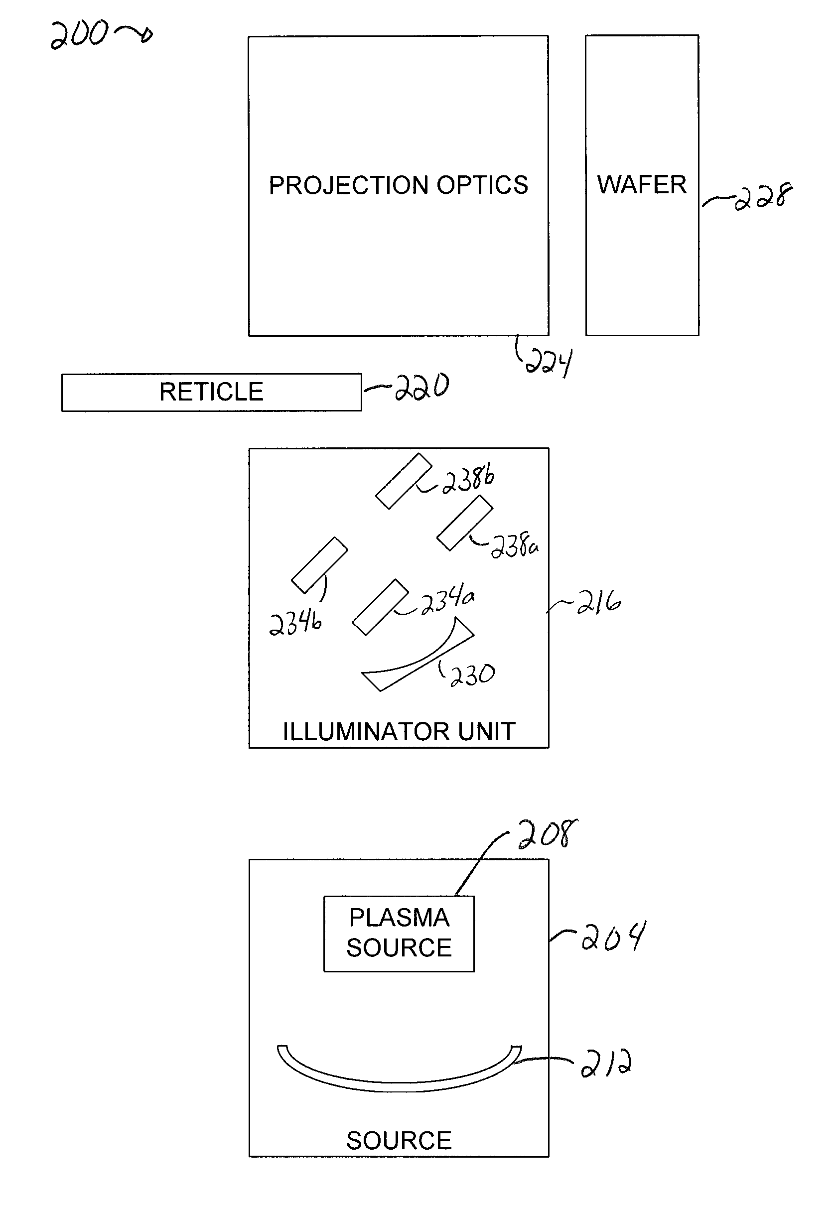
[0042] For instances in which the heat load on a mirror is relatively high, radiant cooling methods are often inadequate for cooling mirrors that are a part of an extreme ultraviolet (EUV) lithography system. Internal or direct cooling methods involving the turbulent flow of fluid may be applied to mirrors to provide cooling in the presence of relatively high heat loads. Though turbulent flow provides for relatively efficient heat transfer and cooling, the use of turbulent flow often results in vibrations within a mirror. Vibrations in the mirror may be transmitted throughout a EUV lithography system, thereby compromising the accuracy of lithography processes.

[0043] An internally cooled mirror which utilizes a coolant or a cooling fluid that undergoes laminar or non-turbulent flow allows the mirror to be cooled substantially without vibrations being induced. Laminar flow is typically characterized by an organized flow field that has streamlines in which viscous stresses are more si...


PUM


Abstract

Methods and apparatus for internally or directly cooling a mirror using a fluid with laminar flow properties are disclosed. According to one aspect of the present invention, an internally cooled mirror includes an optical surface that absorbs light, and at least one microchannel formed beneath the optical surface. The mirror also includes a port that supplied a fluid to the microchannel. The fluid is subjected to a laminar flow and absorbs heat associated with the absorbed light.

Description

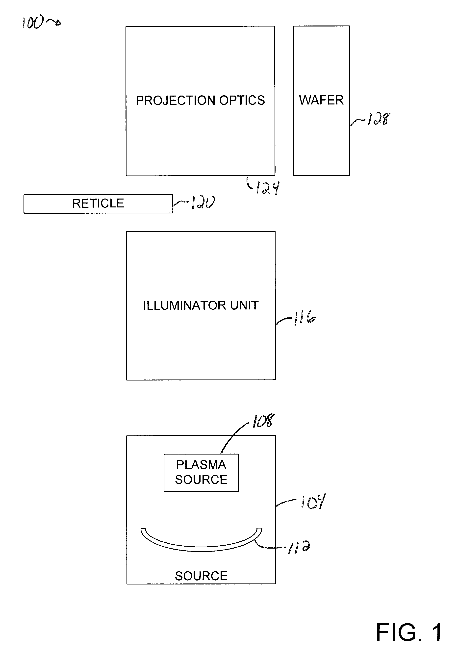
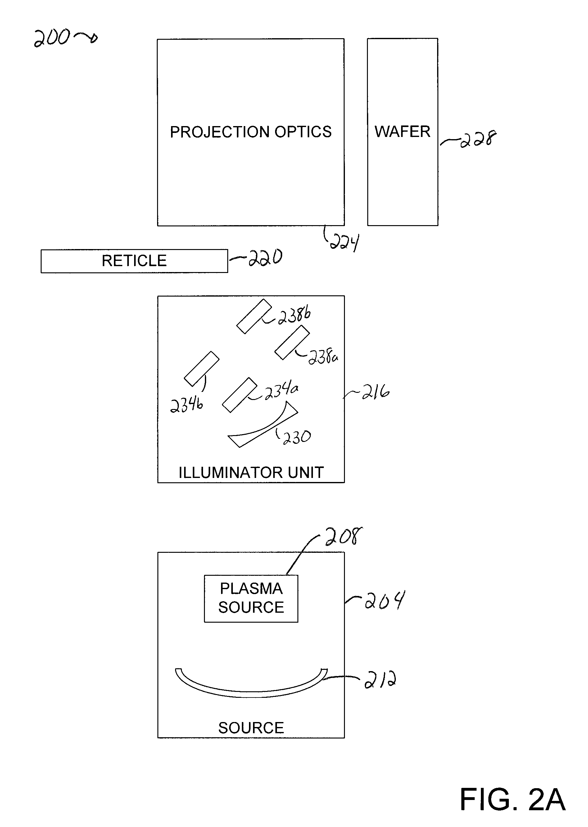
CROSS REFERENCE TO RELATED APPLICATION [0001] The present application claims priority of U.S. Provisional Patent Application No. 60 / 726,321, filed Oct. 13, 2005, which is incorporated herein by reference in its entirety.BACKGROUND OF THE INVENTION [0002] 1. Field of Invention [0003] The present invention relates generally to equipment used in semiconductor processing. More particularly, the present invention relates to an internally cooled mirror that is suitable for use in an extreme ultraviolet lithography system. [0004] 2. Description of the Related Art [0005] Extreme ultraviolet (EUV) lithography is a semiconductor fabrication technology which enables semiconductors with small features, e.g., features with dimensions of approximately 45 nanometers (nm) or less, to be produced. In EUV lithography, a laser heats xenon gas to create a plasma, although there are other method used to make EUV plasmas. Electrons come off the plasma and radiate light. FIG. 1 is a block diagram represen...

Claims


Application Information

Patent Timeline
IPC IPC(8): G02B5/08
CPCG02B5/10G02B7/1815G03F7/70783G03F7/70891G03F7/70983G21K1/06G21K2201/065
Inventor PHILLIPS, ALTON H.COON, DEREKWATSON, DOUGLAS C.
Owner NIKON CORP
Learn More