
Digital broadcasting transmission and reception systems and methods thereof

a digital broadcasting and transmission system technology, applied in data switching networks, error correction/detection using turbo codes, coding, etc., can solve the problems of poor reception performance of atsc vsb systems on weak channels, s. terrestrial-wave digital broadcasting systems, and 1 can not improve the poor reception performance of multi-path channels. , to achieve the effect of improving reception performan

Inactive Publication Date: 2007-04-26
SAMSUNG ELECTRONICS CO LTD
View PDF10 Cites 28 Cited by
  • Summary
  • Abstract
  • Description
  • Claims
  • Application Information

AI Technical Summary

Benefits of technology

[0016] Several aspects and example embodiments of the present invention provide a method for robustly processing and transmitting a digital broadcasting transport stream (TS), digital broadcasting transmission and reception systems, and signal processing methods thereof, which aim to improve reception performance of a terrestrial-wave digital television (DTV) system in the U.S., in accordance with the Advanced Television System Committee (ATSC) vestigial sideband (VSB)through information exchange and mapping with respect to a dual transport stream (TS) including a normal stream and a turbo stream.

Problems solved by technology

Therefore, reception performance of the ATSC VSB system is not good on weak channels, specifically, on a Doppler-fading channel.
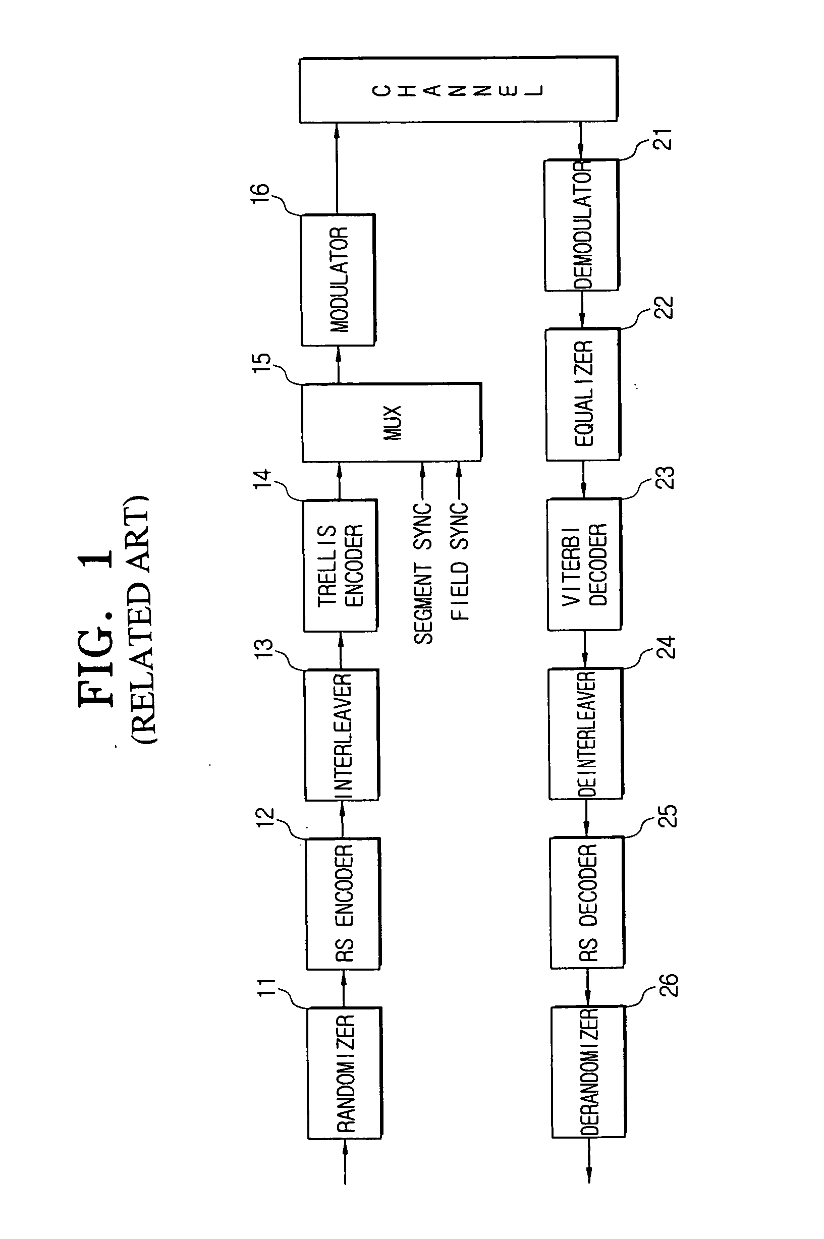
However, the U.S. terrestrial-wave digital broadcasting system as shown in FIG. 1 can not improve the poor reception performance in multi-path channels according to the existing normal data stream transmission although the dual stream is transmitted with the added robust (turbo) data.
That is, the U.S. terrestrial-wave digital broadcasting system is disadvantageous in that the reception performance is not improved at all according to the improved normal stream.
Moreover, the turbo stream does not improve the reception performance greatly in the multi-path environment either.

Method used


Image

  • Digital broadcasting transmission and reception systems and methods thereof
  • Digital broadcasting transmission and reception systems and methods thereof
  • Digital broadcasting transmission and reception systems and methods thereof

Examples


Embodiment Construction

[0149] Reference will now be made in detail to the present embodiments of the present invention, examples of which are illustrated in the accompanying drawings, wherein like reference numerals refer to the like elements throughout. The embodiments are described below in order to explain the present invention by referring to the figures.

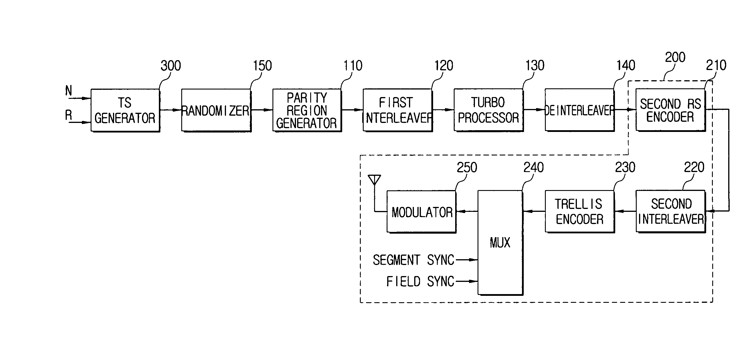
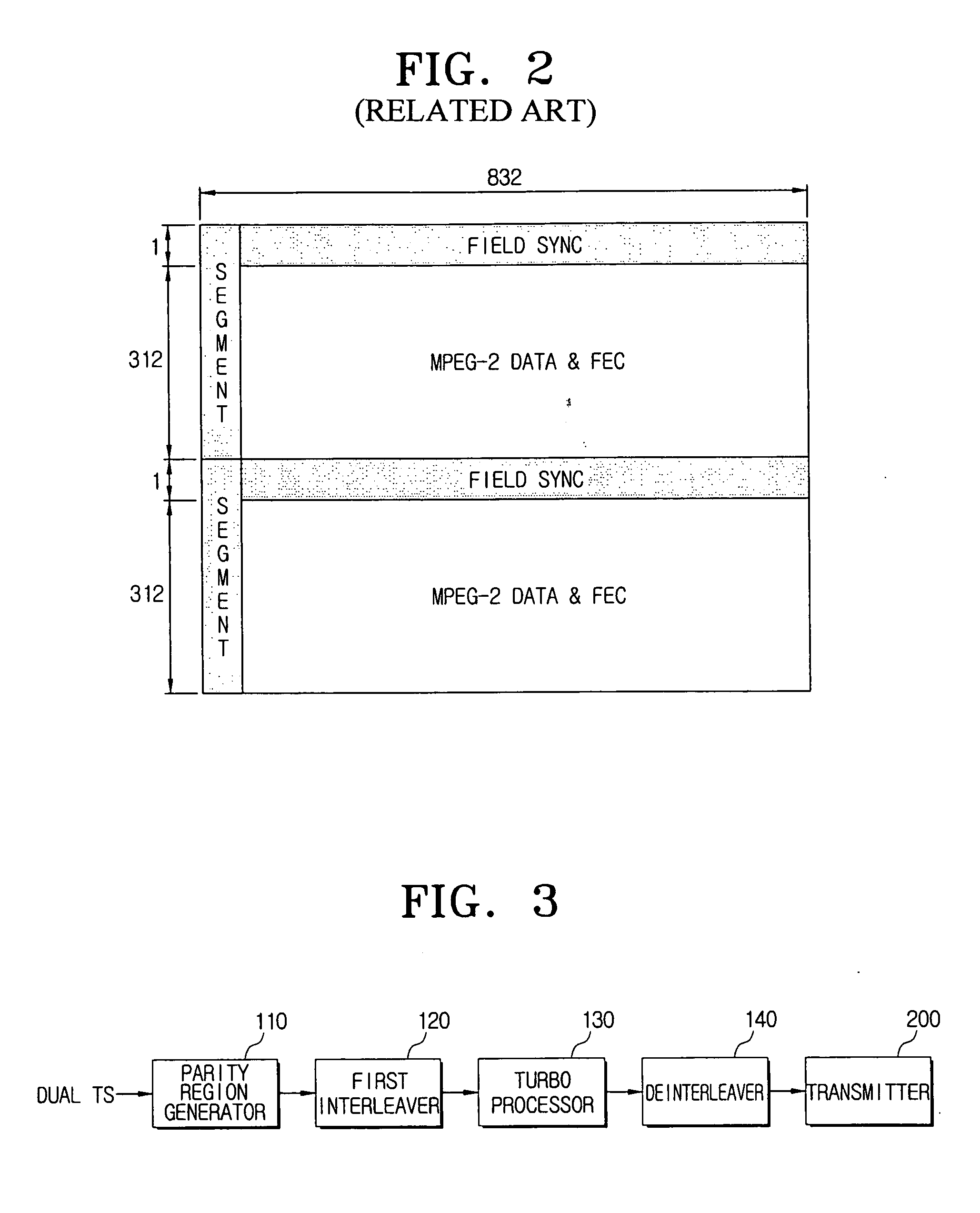
[0150]FIG. 3 is a block diagram of a digital broadcasting transmission system according to an embodiment of the present invention. As shown in FIG. 3, the digital broadcasting transmission system comprises a parity region generator 110, a first interleaver 120, a turbo processor 130, a deinterleaver 140, and a transmitter 150.

[0151] The parity region generator 110 is responsible for generating a parity insertion region with respect to a dual transport stream (TS) including a normal stream and a turbo stream. The parity insertion region denotes a region to which a parity bit calculated for the dual transport stream (TS) is inserted, that is, a region...


PUM


Abstract

A method for processing a dual transport stream (TS) which is multiplexed from a normal stream and a turbo stream is provided for a digital broadcasting transmission / reception system. The digital broadcasting signal processing method includes encoding a dual transport stream (TS) which is multiplexed from a normal steam and a turbo stream; interleaving the encoded dual transport stream (TS); turbo-processing by detecting the turbo stream from the interleaved dual transport stream (TS), encoding the detected turbo stream, stuffing the encoded turbo stream into the dual transport stream (TS), and compensating a parity corresponding to the encoded turbo stream; and trellis-encoding the turbo-processed dual transport stream (TS). Accordingly, the digital broadcasting reception performance can be improved in diverse environments.

Description

CROSS-REFERENCE TO RELATED APPLICATIONS [0001] This application claims the priority from U.S. Provisional Application No. 60 / 728,777, filed on Oct. 21, 2005 in the United States Patent and Trademark Office, U.S. Provisional Application No. 60 / 734,295, filed on Nov. 8, 2005 in the United States Patent and Trademark Office, U.S. Provisional Application No. 60 / 738,050, filed on Nov. 21, 2005 in the United States Patent and Trademark Office, and U.S. Provisional Application No. 60 / 739,448, filed on Nov. 25, 2005 in the United States Patent and Trademark Office, the disclosures of which are incorporated herein by reference.BACKGROUND OF THE INVENTION [0002] 1. Field of the Invention [0003] The present invention generally relates to a method for robustly processing and transmitting a digital broadcasting transport stream (TS), digital broadcasting transmission and reception systems, and signal processing methods thereof. More particularly, the present invention relates to a method for rob...

Claims


Application Information

Patent Timeline
IPC IPC(8): H04L12/56
CPCH03M13/253H03M13/256H03M13/258H03M13/2936H03M13/2957H03M13/6538H04H60/07H04L1/0041H04L1/005H04L1/0054H04L1/0059H04L1/0064H04L1/007H04L1/0071H04L1/009H04L1/08H04L29/06027H04N21/2383H04L65/4076H04L65/607H04L65/611H04L65/70H04L65/1101
Inventor YU, JUNG-PILPARK, EUI-JUNKWON, YONG-SIK
Owner SAMSUNG ELECTRONICS CO LTD
Learn More