Method and apparatus for encoding, method and apparatus for decoding, program, and storage medium

a technology of encoding and decoding apparatus, applied in the direction of color television with bandwidth reduction, signal generator with optical-mechanical scanning, signal generator, etc., can solve the problems of large amount of information, and large amount of data, so as to achieve lossless encoding and small amount of data transmitted to the decoding apparatus

Inactive Publication Date: 2007-04-26
SONY CORP
View PDF7 Cites 10 Cited by
  • Summary
  • Abstract
  • Description
  • Claims
  • Application Information

AI Technical Summary

Benefits of technology

[0034] The preset invention provides an advantage that encoding is performed losslessly.
[0035] Another advantage is that dat...

Problems solved by technology

However, in the encoding method disclosed in Japanese Unexamined Patent Application Publication No. 2000-092328 or Japanese Unexamined Patent Application Publication No. 2000-299866, prediction coefficients are set in advance to fixed values, and thus there is a possibility that a great predicted residual occurs depending on a given image even if pixels used in prediction are properly selected, and thus there is a possibility that the encoded data becomes great in data size.
H08-084336, it is needed to transmit the prediction coeff...

Method used


Image

  • Method and apparatus for encoding, method and apparatus for decoding, program, and storage medium
  • Method and apparatus for encoding, method and apparatus for decoding, program, and storage medium
  • Method and apparatus for encoding, method and apparatus for decoding, program, and storage medium

Examples


first embodiment

[0077] In the following description, an encoding apparatus is first explained, and then a decoding apparatus for decoding data encoded by the encoding apparatus is explained.

Configuration of Encoding Apparatus

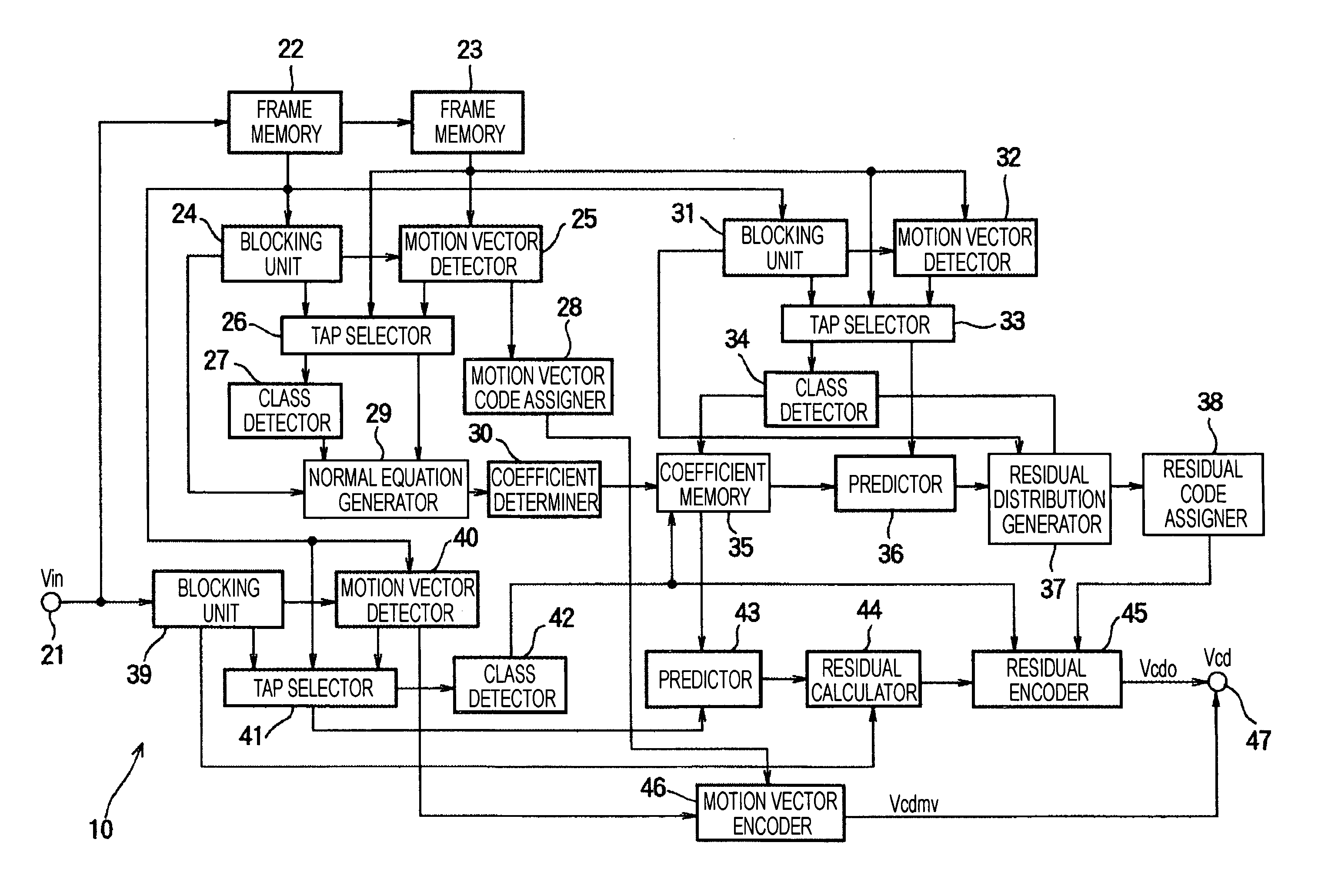
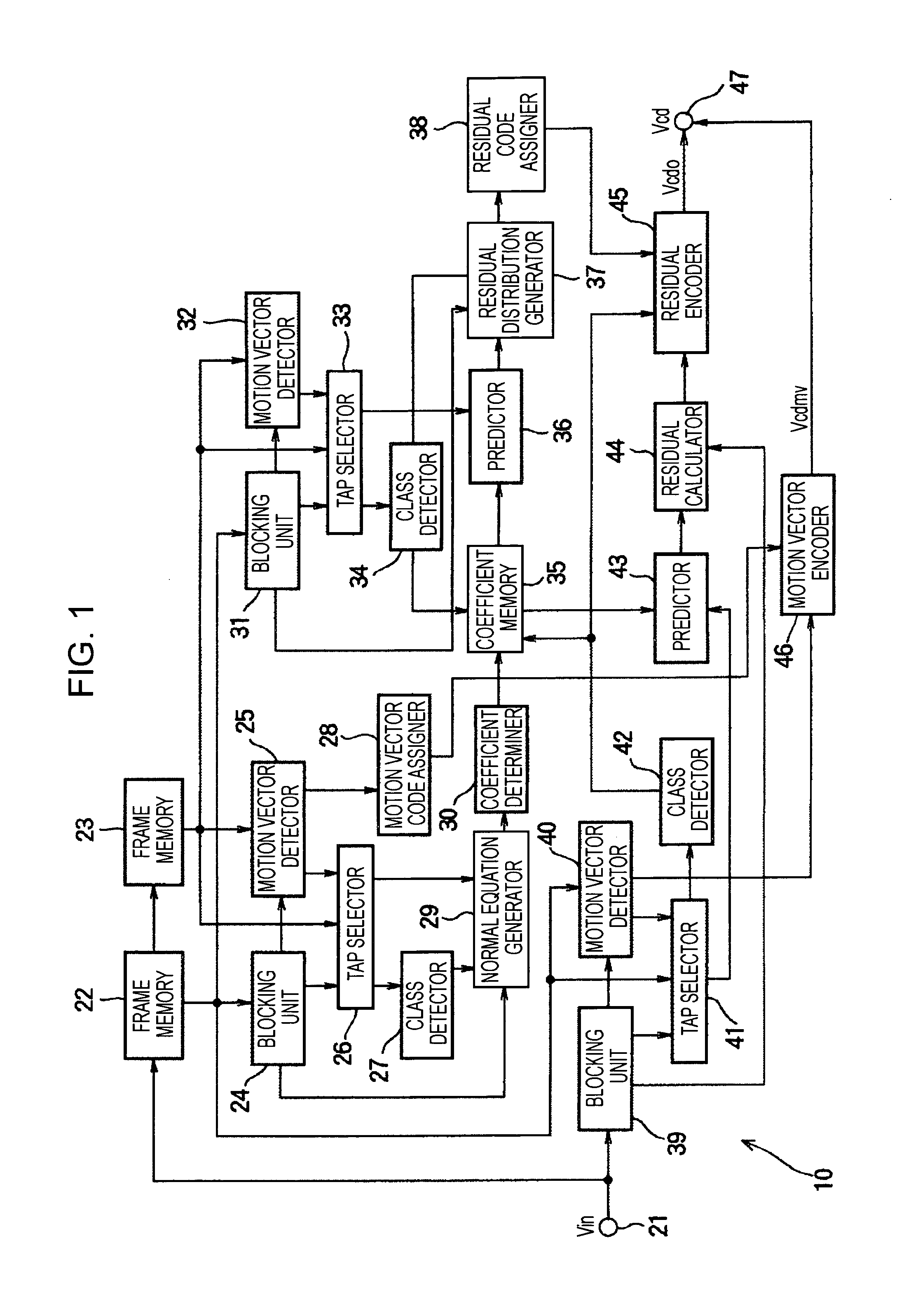
[0078]FIG. 1 is a block diagram showing a configuration of the decoding apparatus according to an embodiment of the present invention. As shown in FIG. 1, the encoding apparatus 10 includes an input terminal 21, a frame memory 22, a frame memory 23, a blocking unit 24, a motion vector detector 25, a tap selector 26, a class detector 27, a motion vector code assigner 28, a normal equation generator 29, a coefficient determiner 30, a blocking unit 31, a motion vector detector 32, a tap selector 33, a class detector 34, a coefficient memory 35, a predictor 36, a residual distribution generator 37, a residual code assigner 38, a blocking unit 39, a motion vector detector 40, a tap selector 41, a class detector 42, a predictor 43, a residual calculator 44, a residual encoder 45, ...

second embodiment

[0258] Another embodiment is disclosed in which encoding is performed using past frames, and decoding is performed using frames which have already been decoded.

Configuration and Operation of Encoding Apparatus

[0259]FIG. 25 shows an example of a configuration of an encoding apparatus according to a second embodiment of the present invention. As shown in FIG. 25, the encoding apparatus 410 includes a residual calculator 411, a linear predictor 412, a storage unit 413, and a prediction coefficient calculator 415. The storage unit 413 includes frame memories 414-1 to 414-4. That is, the encoding apparatus 410 shown in FIG. 25 is configured so as to be capable of storing four frames.

[0260] In the encoding apparatus 410 shown in FIG. 25, data flows as follows. Image data of a frame to be process (encoded) is supplied to the residual calculator 411 and one of the frame memories 414-1 to 414-4 in the storage unit 413. In the following explanation, it is assumed that each time decoding f...


PUM


Abstract

An encoding apparatus is configured to encode input image data including a plurality of frames. The encoding apparatus includes a prediction coefficient generator adapted to generate a prediction coefficient for use in prediction of a second frame from a first frame, an image predictor adapted to generate a predicted image from a third frame by using the prediction coefficient, a residual generator adapted to determine a residual component between a current frame to be encoded and the predicted image, and an output unit adapted to output the residual component in the form of encoded data, wherein the first to third frames are frames which occurred as frames to be encoded, before the occurrence of the current frame.

Description

CROSS REFERENCES TO RELATED APPLICATIONS [0001] The present invention contains subject matter related to Japanese Patent Application JP 2005-306093 filed in the Japanese Patent Office on Oct. 20, 2005, the entire contents of which are incorporated herein by reference. BACKGROUND OF THE INVENTION [0002] 1. Field of the Invention [0003] The present invention relates to a method and apparatus for encoding, a method and apparatus for decoding, a program, and a storage medium, and more particularly, to a method and apparatus for encoding, a method and apparatus for decoding, a program, and a storage medium, which allow it to efficiently perform a prediction process thereby reducing amount of information associated with the prediction. [0004] 2. Description of the Related Art [0005] Encoding can be performed according to one of two methods: a lossless encoding method and a lossy encoding method. In the lossless encoding method, data is encoded in a form that can be decoded into an origina...

Claims


Application Information

Patent Timeline
IPC IPC(8): H04N7/12H04N11/02H04N19/103H04N19/105H04N19/134H04N19/136H04N19/167H04N19/189H04N19/196H04N19/423H04N19/50H04N19/51H04N19/90H04N19/91H04N19/98
CPCH04N19/51H04N19/98H04N19/61
Inventor KONDO, TETSUJIROYASUOKA, TOMOHIROYAMAMOTO, SAKON
Owner SONY CORP
Why Eureka
Try Eureka