Microwave-powered pellet accelerator

a pellet accelerator and microwave technology, applied in the direction of plasma technique, thermonuclear fusion reactor, nuclear reactor, etc., can solve the problems of limiting the velocity of the projectile, presenting additional constraints for consideration, and affecting the output of high-power radiation output, so as to achieve effective interaction and high-power radiation output

Inactive Publication Date: 2007-04-26
GENERAL ATOMICS
View PDF8 Cites 4 Cited by
  • Summary
  • Abstract
  • Description
  • Claims
  • Application Information

AI Technical Summary

Benefits of technology

[0012] As intended for the present invention, the gyrotron will have a high power radiation output that is in a range between approximately one and two megawatts (1-2 MW). Further, the microwave energy in the radiation will preferably be selected to have a wavelength “λ” that will effectively interact with the metallic particles for absorption of the radiation in the pusher medium. In general, wavelengths greater than about one millimeter (λ>1 mm) suffice for this purpose. The import here is to heat and vaporize the deuterium (D2) of the pusher medium and, thereby, cause the pusher medium to expand as a gas. Consequently, as the pusher medium expands, the fuel pellet will be ejected from the waveguide and into the plasma chamber. As envisioned for the present invention, the ejection of fuel pellets can be accomplished at a velocity above three kilometers per second.

Problems solved by technology

These forces then present additional constraints for consideration.
Even when a straight acceleration path is available, access to the path may become a significant concern.
As implied above, for specific instances wherein a projectile must be moved along a path that necessarily includes curves, the tortuous nature of the path can severely limit velocity of the projectile.

Method used


Image

  • Microwave-powered pellet accelerator
  • Microwave-powered pellet accelerator
  • Microwave-powered pellet accelerator

Examples


Embodiment Construction

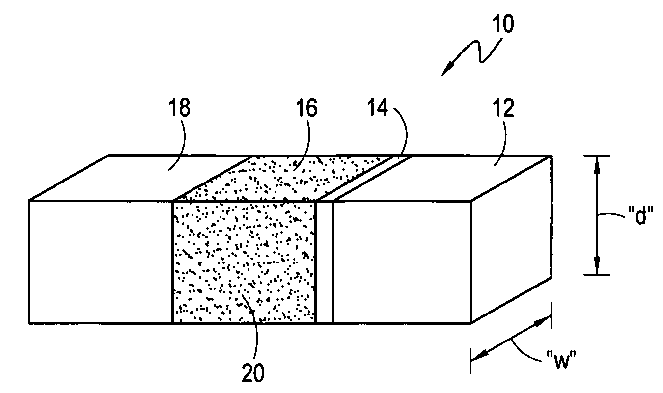
[0020] Referring initially to FIG. 1 a module for use with the systems and methods of the present invention is shown and is generally designated 10. More specifically, FIG. 1 shows that the module 10 includes, in combination, a fuel pellet 12, a reflector 14, a pusher medium 16 and a window 18. For operational reasons, the order in which components of the module 10 are assembled for the present invention is important, and is not arbitrary. Specifically, the reflector 14, if used, is positioned between the fuel pellet 12 and the pusher medium 16, as shown. Note: the reflector 14 may be omitted if desired. If so, then the fuel pellet 12 is juxtaposed with the pusher medium 16. In either case, with or without the reflector 14, the window 18 is juxtaposed with the pusher medium 16, and is positioned in the module 10 opposite the fuel pellet 12.

[0021] In addition to the order in which components of the module 10 are assembled, the materials used for the various components of the module ...


PUM


Abstract

A system for fueling a tokamak includes a gyrotron for radiating microwave energy into a waveguide. Also included is a module having a deutritium-tritium (DT) fuel pellet, a diamond/sapphire window, and a pusher medium located between the pellet and window that is made of frozen deuterium (D2) and metallic particles. With the module in the waveguide, the gyrotron is activated. Radiation from the gyrotron is then directed into the waveguide and through the window to cause a gaseous expansion of the pusher medium. This ejects the pellet from the waveguide and into the plasma of the tokamak.

Description

FIELD OF THE INVENTION [0001] The present invention pertains generally to systems and methods for fueling energy generating apparatus. More particularly, the present invention pertains to systems and methods for injecting fuel pellets into the plasma of a tokamak while controlling the core plasma density in the reactor. The present invention is particularly, but not exclusively, useful for systems and methods that use microwave energy to achieve high velocity fuel pellet injection into the plasma of a tokamak. BACKGROUND OF THE INVENTION [0002] Several applications can be envisioned wherein a projectile needs to be quickly accelerated from standstill to a very high velocity (e.g. 3-5 km / sec). For such applications, there are, obviously, certain constraints that require special consideration. For instance, when the acceleration path of the particle is curved, as opposed to being straight, centrifugal acceleration forces are created on the projectile. These forces then present additio...

Claims


Application Information

Patent Timeline
Patent Type & Authority Applications(United States)
IPC IPC(8): H05H1/22
CPCH05H1/22
Inventor PARKS, PAUL B.PERKINS, FRANCIS W.
Owner GENERAL ATOMICS
Why Eureka
Try Eureka