
Apparatus and Method for Carrying Substrates

Inactive Publication Date: 2007-09-20
PLASMA THERM
View PDF21 Cites 36 Cited by
  • Summary
  • Abstract
  • Description
  • Claims
  • Application Information

AI Technical Summary

Benefits of technology

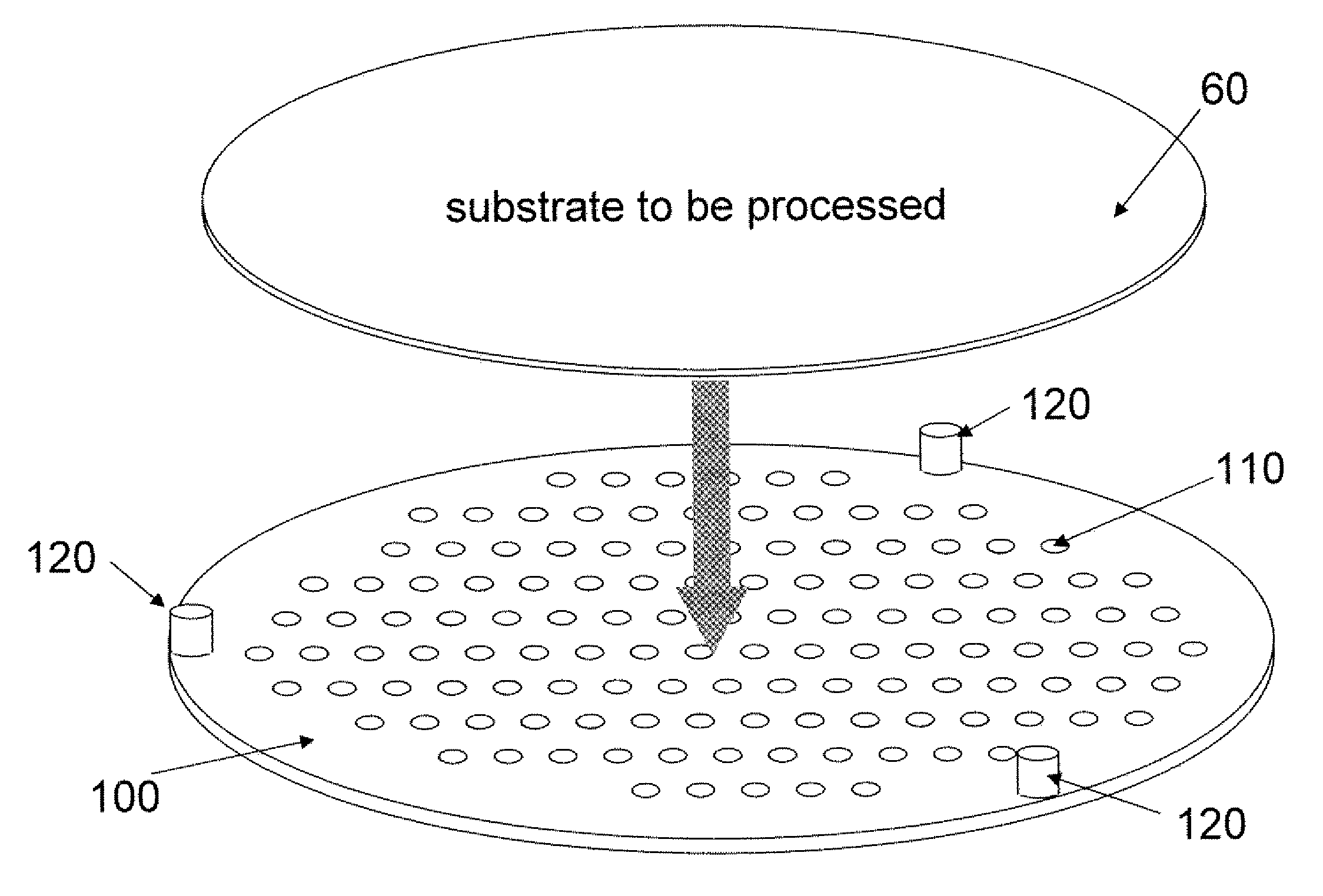
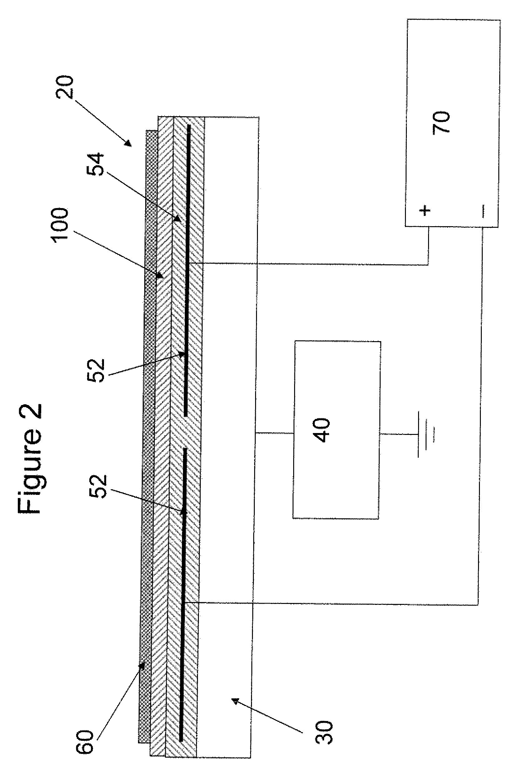
[0019]Another feature of the present invention is to provide an apparatus for carrying at least one substrate for plasma processing. The apparatus comprising a carrier for transporting the substrate onto a substrate support within a plasma processing system. The substrate is located unbonded on the carrier. The positioning of the unbonded substrate on the carrier can be maintained by a plurality of retaining pins or an optional cover plate that creates a recess for the substrate. The cover plate can be integral to the carrier or be a separate part. The cover plate is designed to be resistant to the plasma that will be used to process the substrate. An electrostatic clamp is coupled to the substrate support which electrostatically clamps the substrate to the substrate support through the carrier when the electrostatic clamp is activated. In addition, the carrier can be made of a dielectric material (such as alumina, aluminum oxide ceramic, sapphire or quartz) to effectively interact with the electrostatic force from the electrostatic clamp. The carrier can be designed with a plurality of holes that allow for the conduction of a gas, such as helium, for cooling the backside of the substrate during plasma processing.

Problems solved by technology

This energy results in beat being deposited into the substrate, which, if not removed effectively, will cause a rise in temperature of the substrate.
In some processes this may be used to advantage, but more often an excessive temperature rise produces undesirable side effects such as photo-resist degradation or poor device performance.
The generation of heat is more problematic when high density plasma sources, such as inductively coupled plasma (ICP), are used.
However, a mechanical clamp may cause problems since contact with the front side of the substrate may damage devices or cause particle generation.
Insulating substrates, such as sapphire or quartz, do not clamp efficiently.
It is well known that the use of an ESC can result in some charge remaining on the substrate after the clamping process.
If the residual charge is large enough, the substrate cannot be removed easily from the support which causes problems with the substrate handling mechanism which, in a worse case scenario, can result in a broken or damaged substrate.
The net result is that after processing, the wafer is extremely fragile.
When such fragile wafers are processed using an ESC, any residual charge will cause severe handling problems which will inevitably result in broken wafers.
This causes loss of productivity due to the necessary time required for system recovery from the maintenance necessary to remedy the broken wafers within the plasma processing system.
Problems associated with residual charge are aggravated when the wafer is coated with a dielectric film (e.g., silicon dioxide) since it is difficult for any accumulated charge to neutralize through a nonconductive material.
Placing the substrate on a carrier for transfer and processing can prevent breakage issues, but this does not address the heat removal issue.
However, such a procedure with the necessary de-bonding procedure as described in Weichart is time consuming, potentially contaminating and is likely to increase the chance of damage to thin or fragile substrates due to the additional handling requirements.

Method used


Image

  • Apparatus and Method for Carrying Substrates
  • Apparatus and Method for Carrying Substrates
  • Apparatus and Method for Carrying Substrates

Examples


Embodiment Construction

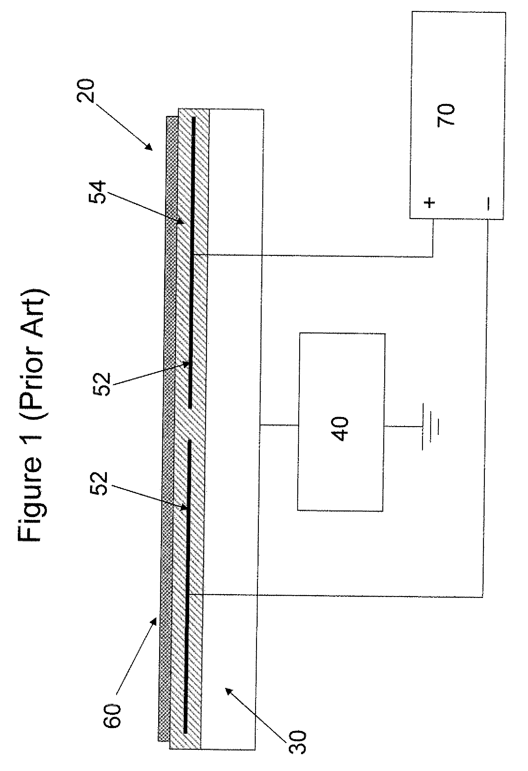
[0029]FIG. 1 depicts the fabrication of a typical Electrostatic Chuck as known in the prior art. As shown, a typical Electrostatic Chuck 20 comprises a substrate support electrode 30 which is typically RF powered 40, though a grounded substrate support may also be used, and on which is built the electrostatic component 50. The electrostatic component 50 consists of one or more electrodes 52 which are isolated from the support member 30 by a dielectric material 54 and is also isolated from the substrate 60 by the same or a different dielectric material 54. A power supply 70 applies a voltage to the electrodes 52. The voltage is usually a dc voltage, but it may be cycled, polarity reversed or pulsed in various manners as is well known in the art. The applied voltage generates an electrostatic attractive force to the substrate 60.

[0030]The magnitude of this force is given by the formula:

F=eo / 2*(V*e / (d+e*g))2

[0031]Where:

[0032]F=generated electrostatic force (in Pascals)

[0033]eo=permitt...


PUM

PropertyMeasurementUnit
Dielectric polarization enthalpyaaaaaaaaaa
Electrical conductoraaaaaaaaaa
Fragilityaaaaaaaaaa

Abstract

The present invention provides a method and an apparatus for carrying at least one substrate for plasma processing. The method and apparatus comprising a carrier for transporting the substrate, that is located unbonded on the carrier, onto a substrate support within a plasma system for plasma processing. An electrostatic clamp, that is coupled to the substrate support, electrostatically secures the substrate to the substrate support through the carrier during plasma processing.

Description

CROSS REFERENCES TO RELATED APPLICATIONS[0001]This application claims priority from and is related to commonly owned U.S. Provisional Patent Application Ser. No. 60 / 783,614 filed Mar. 17, 2006, entitled: Apparatus and Method for Carrying Substrates, this Provisional Patent Application incorporated by reference herein.FIELD OF THE INVENTION[0002]The present invention generally relates to semiconductor processing, and more specifically to the handling of wafers during etch and deposition processes.BACKGROUND[0003]Plasma processing is widely used in the manufacture of both semiconductor and non semiconductor devices which may utilize silicon and other semiconductor substrates (such as GaAs) or materials such as quartz, sapphire or various metallic materials. The processing may involve deposition of different materials or removal of materials (etching) from the substrate. A photo-resist mask is often used to protect areas of the substrate from etching, so that a pattern may be transferr...

Claims


Application Information

Patent Timeline
IPC IPC(8): B23B31/28H01L21/683H01L21/306C23C16/00
CPCH01L21/6831H01L21/68771Y10T29/49998Y10T279/23B25B11/00
Inventor JOHNSON, DAVIDLAI, SHOULIANG
Owner PLASMA THERM
Learn More