
Site marker visible under multiple modalities

Active Publication Date: 2007-04-26
SUROS SURGICAL SYST
View PDF77 Cites 58 Cited by
  • Summary
  • Abstract
  • Description
  • Claims
  • Application Information

AI Technical Summary

Benefits of technology

[0009] A site marker is provided that includes a generally hollow body defining a cavity. The site marker is formed into a predeployment configuration whereby the site marker is compressed into a predetermined size and shape to as to be readily positionable within a deployment device. The site marker expands from the first predeployment position to a second post deployment configuration upon insertion into the body. A thread or deployment line (e.g., thread, filament, wire) is attached to and extends between a forward end and a rearward end of the body portion. At least one marker element with a thr

Problems solved by technology

Known biopsy site markers have been found to have disadvantages in that the site markers are not visible under all available modalities.
Moreover, because of this problem, when cancer is found at a biopsy site that has been previously marked with a site marker, due to the poor visibility of the biopsy site marker under ultrasound or other visualization modalities, the patient must undergo an additional procedure that places an additional device the biopsy site to enable the surgeon to find the biopsy site in subsequent procedures.

Method used


Image

  • Site marker visible under multiple modalities
  • Site marker visible under multiple modalities
  • Site marker visible under multiple modalities

Examples


Embodiment Construction

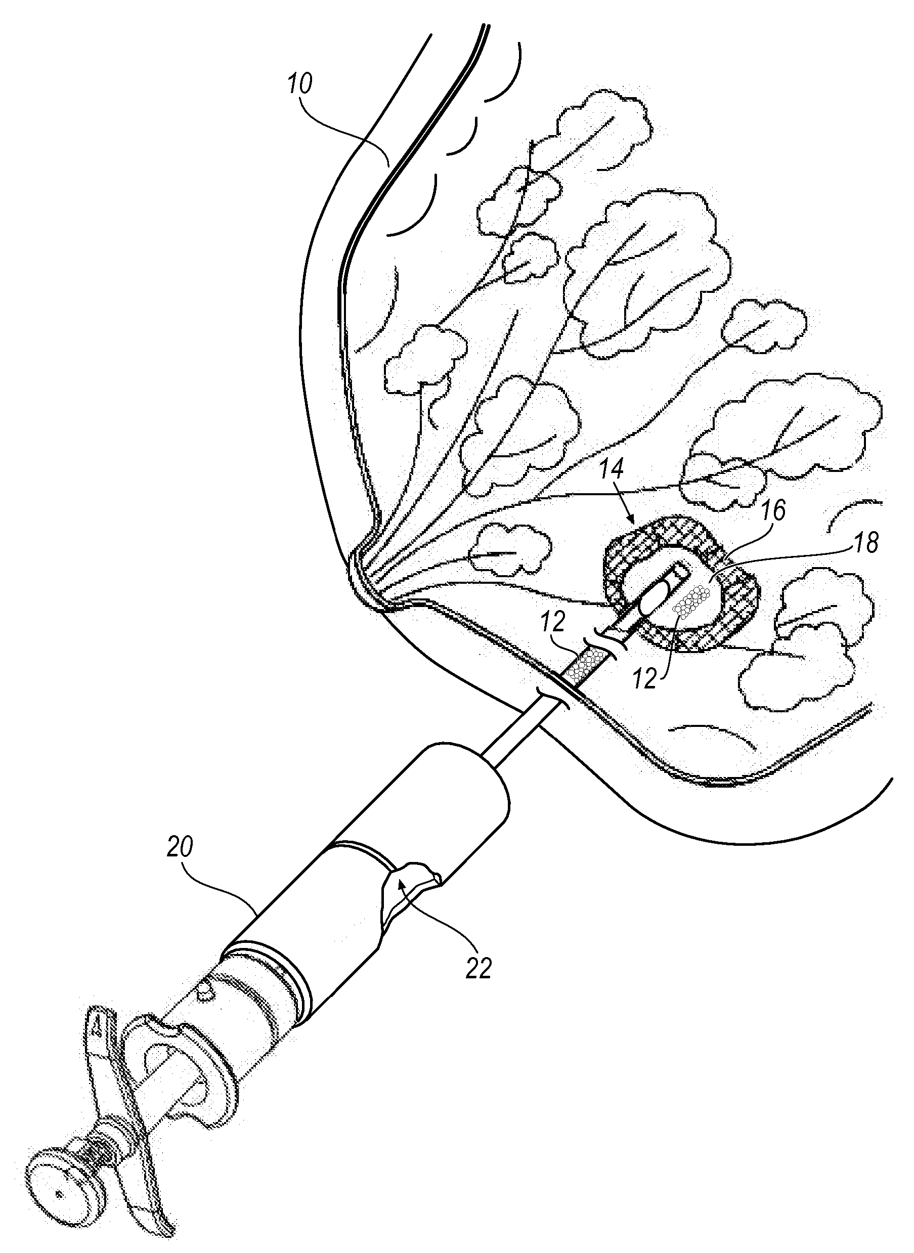
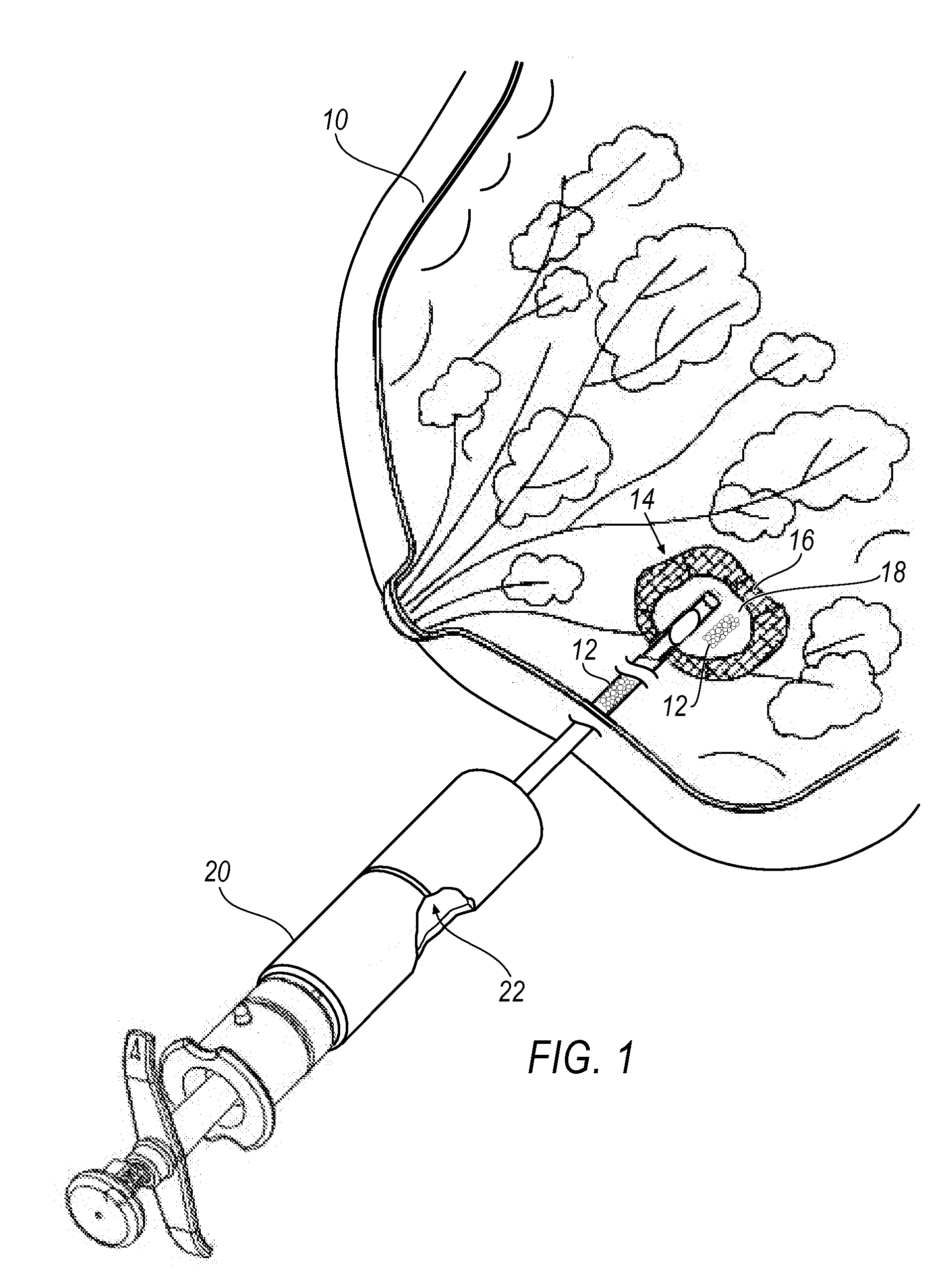
[0051]FIG. 1 illustrates a perspective view of a human breast 10 being implanted with a site marker 12 according to an embodiment of the present invention. At a biopsy site 14 is a lesion 16 from which a tissue sample has been removed, resulting in a biopsy cavity 18. One or more site markers 12 are implanted in the biopsy cavity 18 using a marker delivery system 20, as shown in FIG. 1. In one embodiment, the marker delivery system 20 is slidably advanced through an inner lumen 22 of a biopsy device (not shown), which avoids the need to withdraw the biopsy device and thereafter insert the marker delivery system 20. Delivering the site marker 12 in the biopsy cavity 18 without withdrawing the biopsy device reduces the amount of tissue damage and enables more accurate placement of the site marker 12. The marker delivery system 20 illustrated in FIG. 1 is exemplary only and it is understood that the site marker embodiments disclosed herein are suitable for use with other marker deliver...


PUM


Abstract

A site marker is provided that includes a generally hollow body defining a cavity. A deployment line within the site marker positions at least one marker element within the body portion. The deployment line has a first end that is fixedly secured to a first end of the body portion and a second end that is secured to a second end of the body portion. The deployment line is pre-biased so as to pull the first end of the body portion towards the second end of the body portion, and thereby expand the body portion.

Description

CROSS REFERENCE TO RELATED APPLICATIONS [0001] This application is a Continuation-in-part of U.S. application Ser. No. 11 / 242,334, entitled SITE MARKER VISIBLE UNDER MULTIPLE MODALITIES, filed Oct. 3, 2005 which is a Continuation-in-part of U.S. application Ser. No. 10 / 964,087, entitled SITE MARKER VISIBLE UNDER MULTIPLE MODALITIES, filed Oct. 13, 2004.FIELD OF THE INVENTION [0002] The present invention relates generally to site markers for breast biopsy procedures. More specifically, the present invention relates to site markers that are visible under multiple modalities. BACKGROUND OF THE INVENTION [0003] In the diagnosis and treatment of breast cancer, it is often necessary to perform a biopsy to remove tissue samples from a suspicious mass. The suspicious mass is typically discovered during a preliminary examination involving visual examination, palpation, X-ray, magnetic resonance imaging (MRI), ultrasound imaging or other detection means. [0004] When a suspicious mass is detec...

Claims


Application Information

Patent Timeline
IPC IPC(8): A61B10/00
CPCA61B19/54A61B2017/00004A61B2017/00867A61B2019/5408A61B2019/5425A61B90/39A61B2090/3908A61B2090/3925
Inventor LEOPOLD, PHILLIP M.NICOSON, ZACHARY R.
Owner SUROS SURGICAL SYST
Learn More