
Medical Illumination Device with Sterile Packaging

a medical illumination and sterile packaging technology, applied in the field of medical illumination devices with sterile packaging, can solve the problems of promoting increased cell death and drying out exposed patient tissue, and achieve the effects of high intensity, convenient positioning, and convenient selection

Inactive Publication Date: 2007-04-12
SHEA TODD +1
View PDF32 Cites 7 Cited by
  • Summary
  • Abstract
  • Description
  • Claims
  • Application Information

AI Technical Summary

Benefits of technology

[0011] One aspect of the invention includes a self contained, compact, selectively mountable, easily positionable, portable, high intensity, low heat producing light source.
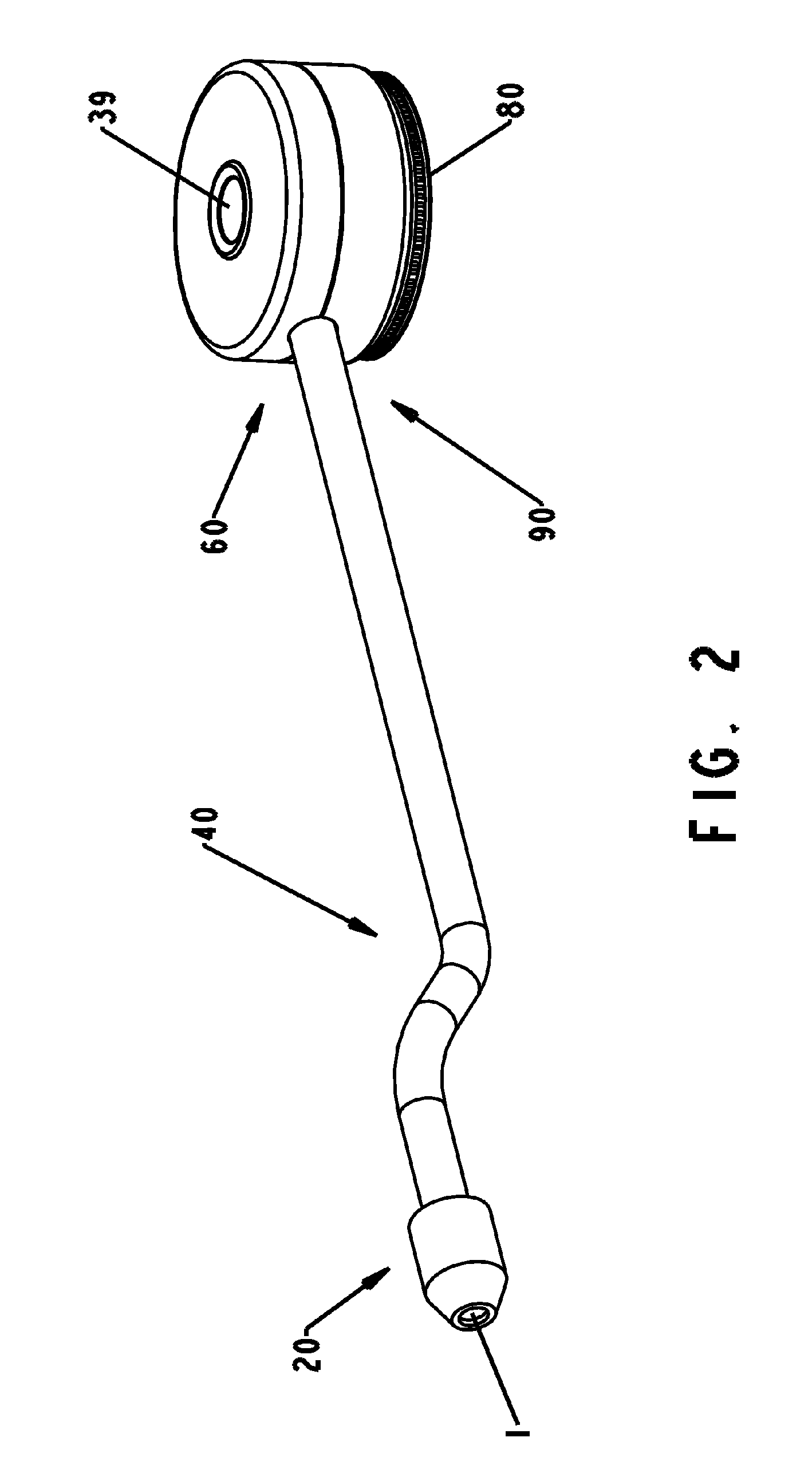
[0012] This aspect of the invention overcomes the problem of a non-sterile light source that can be used in close proximity to the area of interest due to its self contained, compact, and sterile properties. The selective mounting base allows the device to be mounted on a number of surfaces including operative drapes, patient's clothes (for emergency field use) and other convenient areas to illuminate the patient site. With the removable mounting ability, the device may be connected relative to the patient so its orientation will not change with instrumentation or operative staff motion. The easily directable body of the device allows for relatively instantaneous unlimited orientation adjustment of the light beam direction without relocating the mounting base.
[0013] Because the intensity of light is related by the inverse square of the distance from the light, it often takes a very intense, high-powered light located overhead of the medical personnel to provide enough illumination. Such a high intensity light can create significant heat, which can dry out exposed patient tissue and promote increased cell death. Having a low heat producing light source so close to the focus of interest requires less intense light and less chance of tissue damage. With the light source in such close proximity to the focal area of interest, blocking the light by surgical team members or instrumentation is less likely, thus promoting a more efficient and faster surgery.

Problems solved by technology

Such a high intensity light can create significant heat, which can dry out exposed patient tissue and promote increased cell death.

Method used


Image

  • Medical Illumination Device with Sterile Packaging
  • Medical Illumination Device with Sterile Packaging
  • Medical Illumination Device with Sterile Packaging

Examples


Embodiment Construction

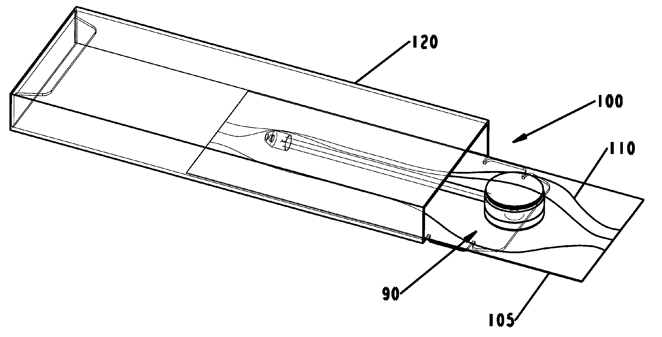
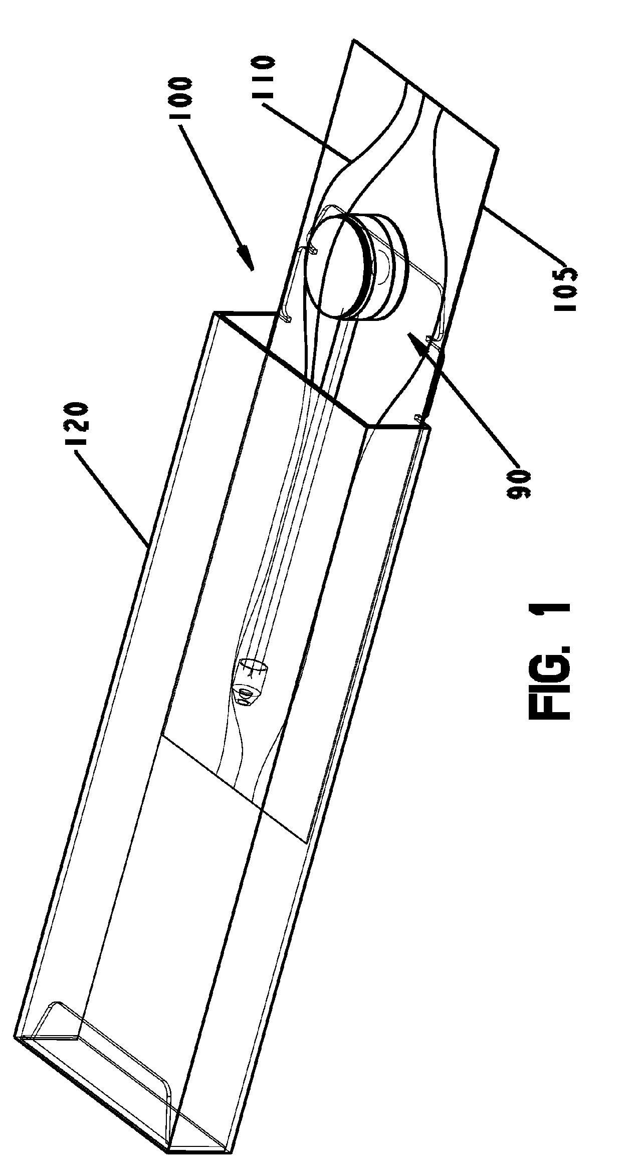
[0037] Generally, one embodiment of the system consists of a medical illumination device packaged within a sterile package. Referring to FIG. 1, medical illumination device 90, is shown packaged within sterile package 100, and partially inserted into a shipping box 120. Shipping box 120 is used for shipping and storage of the medical illumination device 90 in the sterile condition. Sterile package 100 consists of a back 105 and a cover 110, that are sealed to one another, completely surrounding medical illumination device 90. When medical illumination device 90 is sterilized, as long as sterile package 100 is not opened, the device will remain sterile until use of the device is desired. Back 105 and cover 110 may consist of Tyvek®, foil, plastic, or other coated paper or polymer that maintains a barrier impervious to contaminants and maintains sterility, such as a sterility assurance level of 1×10⁻⁶. When illumination device 90 is desired for use, the user removes package 100 from b...


PUM


Abstract

A medical illumination device including a sterile package, a base, a light housing, and a flexible body. An attachment component of the base may include an adhesive exposable upon removal of the component from the package. The base may have sufficient surface area, sufficient base weight, and sufficient holding strength to effectively provide stability for repositioning. The base may be 50% of the device weight and have a surface area of 1.0 square inch. A second portion of the attachment component may be repositionable without detaching the first portion. Portions may be separately removable from the sterile package. The device may include a second flexible body attaching a second light source to the base. The device may provide a base containing a power means, a lighting means, and a flexible body means. The device may also include a sterile packaging means and repositioning means.

Description

[0001] The present invention relates to the field of medical, surgical, and dental illumination devices. More particularly, this invention relates to an illumination device that includes a stable base and is also self-contained, compact, flexible, portable, high intensity, and low heat producing and readily contained in a sterile package. The present invention also overcomes problems of handless stability as well as sterility in various medical environments, especially in emergency response situations where other sterile light sources are not readily available. BACKGROUND OF INVENTION [0002] A significant part of any medical procedure, therapy, or assessment is an adequate light source to provide the user with a highly perceptible view of the area of interest. Many sources of illumination are currently used to provide diffuse lighting, but supply inadequate lighting of specific areas of interest. The areas of interest may include small structures, deep spaces, or within small incisi...

Claims


Application Information

Patent Timeline
IPC IPC(8): F21V17/00
CPCA61B5/6833A61B19/52A61B19/5202A61B2017/00734A61B2562/242A61B90/36A61B90/30A61B90/35
Inventor SHEA, TODDARNAL, KEVIN
Owner SHEA TODD
Learn More