Insulin pump

a technology of insulin pump and push rod, which is applied in the direction of medical devices, intravenous devices, medical devices, etc., can solve the problems of deterioration inability of the piston to carry out a stable and smooth advancing motion, and relatively reduced contact area between the male screw of the rotary shaft and the female screw of the push rod, so as to improve the durability of the piston

Inactive Publication Date: 2007-04-26
ENTER TECH +2
View PDF12 Cites 58 Cited by
  • Summary
  • Abstract
  • Description
  • Claims
  • Application Information

AI Technical Summary

Benefits of technology

[0007] Accordingly, the present invention has been made in view of the above problems, and it is an object of the present invention to provide an automatic insulin pump, which allows the rotary shaft to only serve rotate piston advancing means (push plate assembly) to remove vertical load applied to a rotary shaft, thereby improving durability thereof.

Problems solved by technology

However, the conventional automatic insulin pump has a problem in that lots of vertical load is applied to the rotary shaft as the rotary shaft is directed connected to the piston to drive the piston, and thereby, durability of the rotary shaft is deteriorated.
Furthermore, the conventional automatic insulin pump has another problem in that a contact area between the male screw of the rotary shaft and the female screw of the push member is relatively reduced as the diameter of the rotary shaft becomes small, and thereby, the piston cannot carry out a stable and smooth advancing motion.

Method used


Image

  • Insulin pump
  • Insulin pump
  • Insulin pump

Examples


Embodiment Construction

[0020] The present invention will now be described in detail in connection with preferred embodiments with reference to the accompanying drawings.

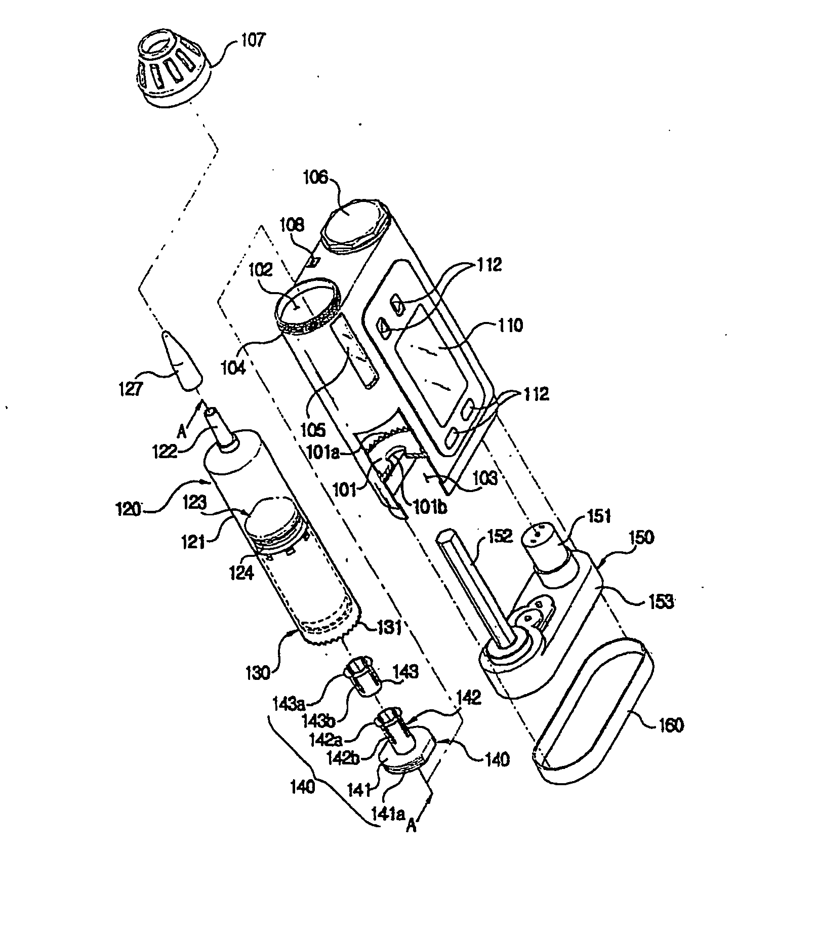
[0021]FIG. 5 is a generally perspective view of an automatic insulin pump according to a preferred embodiment of the present invention, and FIG. 6 is an exploded perspective view of the automatic insulin pump of the present invention. As shown in FIGS. 5 and 6, the automatic insulin pump according to the present invention has an injector 120 contained inside a small box type housing 100. For this, the housing 100 has a cylindrical injector receiving space 102 formed at a side of the inside of the housing 100 in a longitudinal direction. The housing 100 has a battery space (not shown) formed at an appropriate position thereof for supplying electric power to various electric components. The reference numeral 106 designates a battery cover for restricting a battery (not shown) inside the battery space. The housing 100 also includes an LCD wi...


PUM


Abstract

The present relates to an automatic insulin pump, which allows the rotary shaft only to rotate piston advancing means to remove vertical load applied to a rotary shaft, thereby improving durability thereof. The insulin pump includes: an injector having a syringe for containing insulin therein, and a piston inserted into the rear end of the syringe for providing the syringe with insulin discharge pressure; a housing having an injector receiving space formed in an appropriate position thereof, the injector receiving space having a partition wall formed at the rear end thereof; a rotary shaft having a non-circular section and a predetermined length; power supply means for rotating the rotary shaft at a predetermined speed; a push plate assembly for providing the piston with ahead power by pushing the piston, the push plate assembly having a disk part having a male screw formed on the outer circumferential surface thereof and a coupling hole axially coupled with the rotary shaft at the central portion thereof to allow for forward and backward movement of the rotary shaft, which passes through the coupling hole; and a hollow cylindrical type push plate case inserted into the injector receiving space of the rear end of the syringe, for the piston to pass therethrough, the push plate case having a female screw formed on the inner circumferential surface thereof to be coupled with the male screw of the disk part for allowing the disk part to carry out a spirally forward and backward movement.

Description

TECHNICAL FIELD [0001] The present invention relates to an automatic insulin pump, and more particularly, to an automatic insulin pump, which can reduce load applied to a rotary shaft providing ahead power to a piston to thereby improve durability thereof. BACKGROUND ART [0002] In general, in a parenteral therapy for a glycosuria patient, the glycosuria patient or a protector for the glycosuria patient injects insulin into the patient twice or three times a day. At this time, the amount of insulin needed for the patient varies according to time and patient's body conditions. For example, more insulin needs to be injected during taking a meal than in normal times. However, the conventional method for manually injecting insulin has several disadvantages in that it is impossible to inject an exact amount of insulin to the patient, and in that the patient suffers from an inconvenience of going to a hospital to administer insulin more than insulin injected in normal times. [0003] To solv...

Claims


Application Information

Patent Timeline
Patent Type & Authority Applications(United States)
IPC IPC(8): A61M37/00A61M5/20A61M5/145
CPCA61M5/14566A61M5/20
Inventor JAN, KIL-WANNAM, YONG-TAEGMOON, CHI-HWAN
Owner ENTER TECH
Why Eureka
Try Eureka