Spinal distraction device and methods of manufacture and use

a technology of distraction device and spinal cord, which is applied in the field of spinal cord distraction device, can solve the problems of pain and discomfort, debilitating and achieves the effects of improving spinal stability, reducing pain and discomfort, and reducing spa

Inactive Publication Date: 2007-04-26
NUVASIVE
View PDF9 Cites 100 Cited by
  • Summary
  • Abstract
  • Description
  • Claims
  • Application Information

AI Technical Summary

Benefits of technology

[0010] In view of the foregoing, it is an object of the present invention to provide a spinal distraction device that overcomes the drawbacks of previously known treatments and devices, and which may be implanted using open surgical, minimally invasive or percutaneous implantation techniques.

Problems solved by technology

The conditions often cause pain and discomfort that may, in severe cases, be debilitating.
In some cases, the space may be reduced to such a degree that the spinal column, nerves and / or blood vessels become impinged, or compressed, causing pain and / or numbness.
That instability may exacerbate or independently cause compression of the spinal cord, nerves and / or blood vessels within and surrounding the spine.
A common problem with such procedures is that they are very invasive and require the severing of tissues surrounding the vertebral bodies causing the compression.
As a result, the patient is oftentimes subjected to lengthy rehabilitation.
In addition, some patients, especially elderly patients, may not have the stamina to endure such invasive procedures or lengthy rehabilitation.
A disadvantage of the device is that where fusion between the spinous processes is desired, the device is inadequate because it is designed and constructed so that there is relative movement.

Method used


Image

  • Spinal distraction device and methods of manufacture and use
  • Spinal distraction device and methods of manufacture and use
  • Spinal distraction device and methods of manufacture and use

Examples


Embodiment Construction

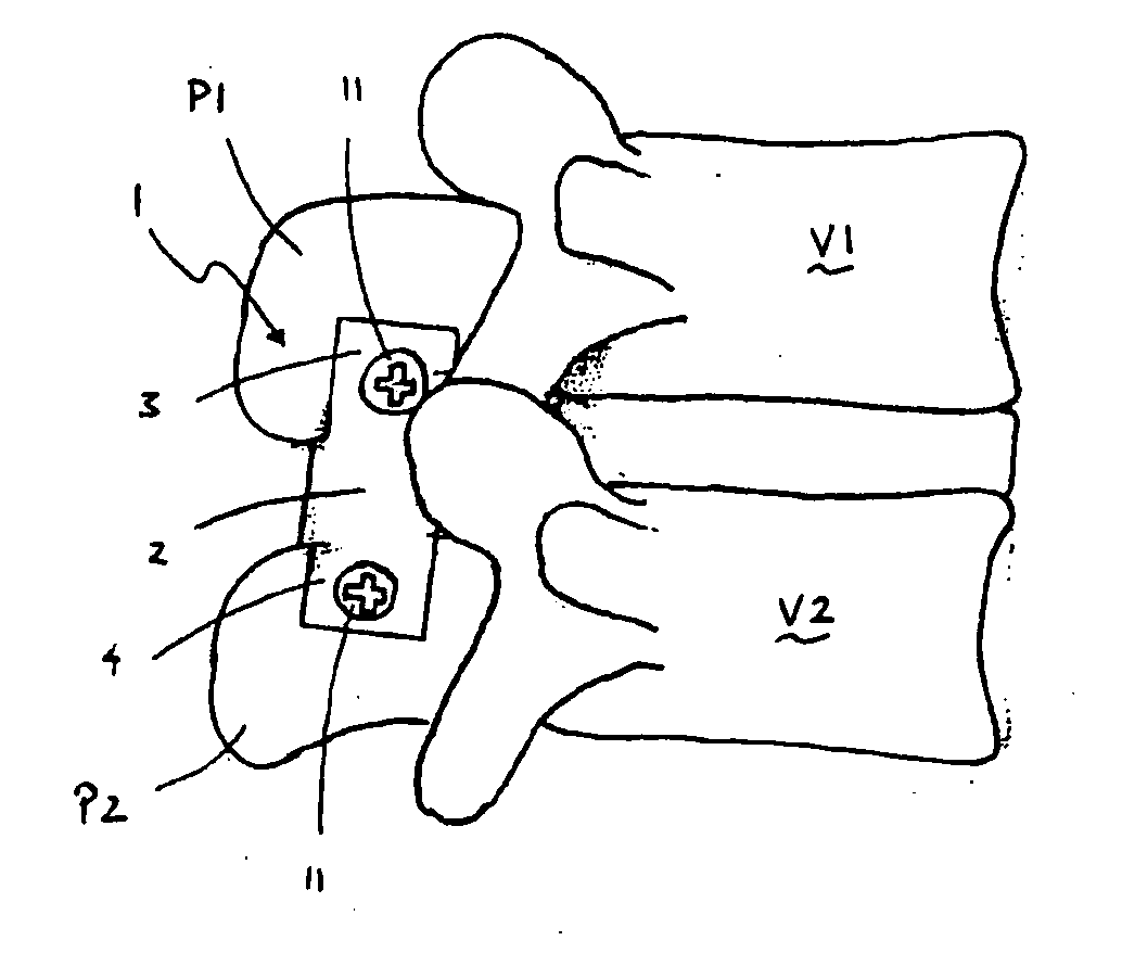
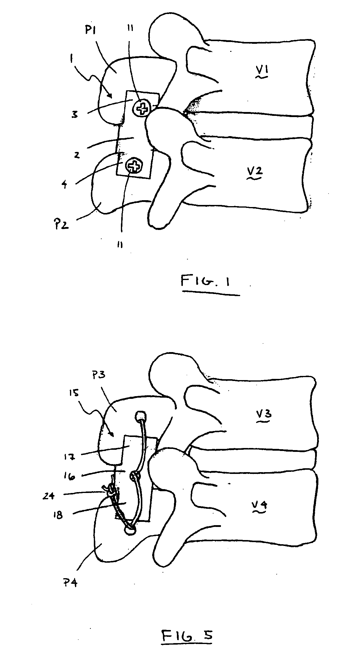
[0025] The present invention is directed to a spinal distraction device 1 that is used to maintain a desired space between adjacent spinous processes, as shown in FIG. 1-4. Distraction device 1 may be implanted between adjacent vertebrae V1 and V2 to maintain a desired space between the vertebrae. In particular, the distance between a superior spinous process P1 of a superior, or upper, vertebra V1 and an inferior spinous process P2 of inferior, or lower, vertebra V2 is maintained by distraction device 1.

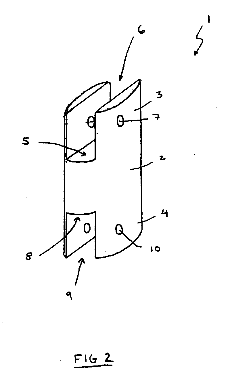
[0026] Distraction device 1 is generally H-shaped and generally includes a main body portion 2, a pair of superior side walls 3, and a pair of inferior side walls 4. Body portion 2 is a generally columnar member that has a height H1 corresponding to the desired space between adjacent spinous processes. As shown, body portion 2 has an oval cross-section, but it shall be appreciated that body portion 2 may have any cross-sectional shape, such as a rectangle, circle or semi-circle and...


PUM


Abstract

A spinal distraction device is provided having a generally H-shaped cross section that maintains a desired space between adjacent spinous processes. The distraction device includes a body and two pairs of parallel sidewalls. The sidewalls create channels for receiving respective spinous processes. The distraction device is fused to the spinous processes with fixation devices.

Description

CROSS-REFERENCE TO RELATED APPLICATION [0001] This application claims priority to U.S. Provisional Patent Application Ser. No. 60 / 722,208, filed Sep. 29, 2005, which is hereby incorporated in its entirety by reference herein.FIELD OF THE INVENTION [0002] The present invention relates to devices for improving the spinal stability of a patient. More particularly, the present invention relates to a spinal distraction device that may be implanted between adjacent spinous processes and is particularly well suited for percutaneous delivery. BACKGROUND OF THE INVENTION [0003] As people age, they often experience degenerative conditions affecting the spinal structures. The conditions often cause pain and discomfort that may, in severe cases, be debilitating. Those conditions may include, for example, spinal stenosis, facet arthropathy and degenerative disc disease. [0004] Spinal stenosis is the thickening of the bones that make up the spine. That thickening often reduces the size of the pas...

Claims


Application Information

Patent Timeline
Patent Type & Authority Applications(United States)
IPC IPC(8): A61F2/30
CPCA61B17/7062
Inventor BOOTH, KEVIN C.GRANT, JOSEPH M.
Owner NUVASIVE
Why Eureka
Try Eureka