Methods and Apparatus for Making Placement Sensitive Logic Modifications

a logic modification and logic technology, applied in the direction of error detection/correction, instruments, cad circuit design, etc., can solve the problems of large-scale modification of an existing chip design that can be exceptionally difficult, work using such a prior technique would generally have a negative impact on the design cycle, time to market, and design reuse, so as to shorten the design cycle and reduce risk. , the effect of reducing the design and development tim

Inactive Publication Date: 2007-04-26
BELL SEMICON LLC
View PDF3 Cites 32 Cited by
  • Summary
  • Abstract
  • Description
  • Claims
  • Application Information

AI Technical Summary

Benefits of technology

[0005] Among its several aspects, the present invention recognizes that to minimize design and development time, it is desirable to develop an automated placement sensitive process for making logic modifications. The automated placement sensitive process would allow for a large scale addition of random logic and flip-flops (flops) with minimum disruption to an existing database, while obeying all the constraints and rules required for built in self test (BIST). Such an automated placement sensitive process for handling engineering change orders would allow for significant reuse of an existing chip database, shortening design cycles and making them more predictable, reducing risk, and providing a substantial savings in resources.

Problems solved by technology

These modifications may require significant changes with the addition of relatively large functional blocks and changes to existing logic functions.
Large-scale modifications to an existing chip design can be exceptionally difficult due to the absence of an automated process to change the existing chip design while satisfying strict connectivity, scan chain length, data transfer requirements of design for test (DFT), and timing requirements of BIST.
The amount of work using such a prior technique would generally have a negative impact on the design cycle, time to market, and design reuse.
In addition, the earlier verified database for the existing chip design, that was verified by the corresponding working silicon, could be completely lost due to the change process for the modifications required during implementing the changes on chip and that would substantially increase risk.

Method used


Image

  • Methods and Apparatus for Making Placement Sensitive Logic Modifications
  • Methods and Apparatus for Making Placement Sensitive Logic Modifications
  • Methods and Apparatus for Making Placement Sensitive Logic Modifications

Examples


Embodiment Construction

[0023] The present invention will now be described more fully with reference to the accompanying drawings, in which several embodiments and various aspects of the invention are shown. This invention may, however, be embodied in various forms and should not be construed as being limited to the embodiments set forth herein. Rather, these embodiments are provided so that this disclosure will be thorough and complete, and will fully convey the scope of the invention to those skilled in the art.

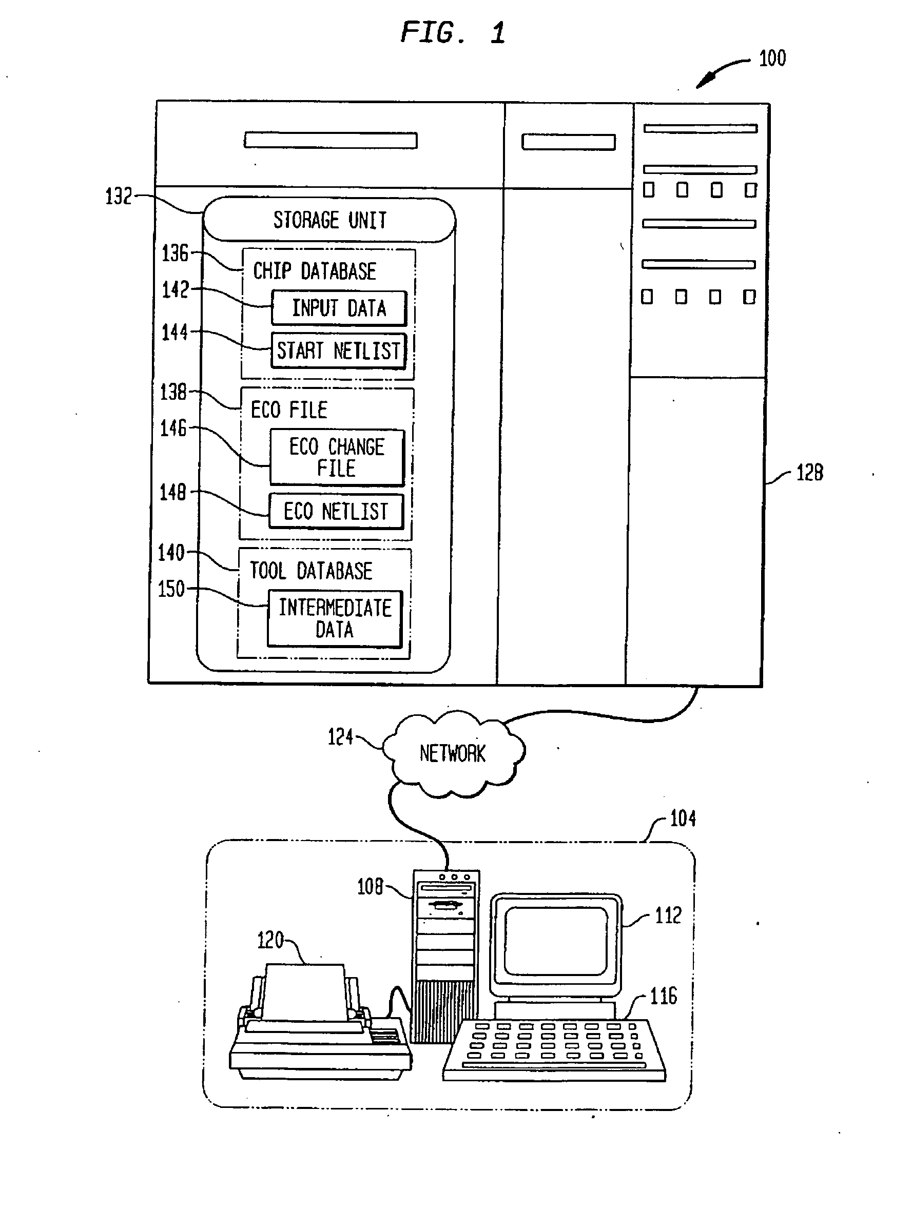
[0024]FIG. 1 illustrates an automated change design systems 100 in accordance with an embodiment of the present invention. The automated change design system 100 may suitably include a work station 104 consisting, for example, of a processor complex 108, a monitor 112, a keyboard / mouse 116, and may include a printer 120. The work station 104 is connected to a network 124. This connection may be made utilizing the Internet or a local intra-net, for example. The network 124 is then further connecte...


PUM


Abstract

Methods and apparatus are described for making a placement sensitive engineering change to meet design for test requirements. One of the methods includes placing a set of new flops in an already placed chip design to meet functional requirements of an engineering change. The already placed chip design is pruned to create a set of valid flops and valid scan chains based on a set of pruning rules. A unified flop database is generated containing physical location and connection information for the new flops and the set of valid flops. A change file for the new flops, selected valid flops, and valid scan chains associated with the selected valid flops is generated meeting allocation and placement sensitive signal connection rules. The new flops are connected to the selected valid flops allowing design for test requirements to be met

Description

RELATED U.S. APPLICATION DATA [0001] The present application claims the benefit of U.S. Provisional Application No. 60 / 728,451, filed Oct. 20, 2005 which is incorporated by reference herein in its entirety.FIELD OF THE INVENTION [0002] The present invention relates generally to improved methods and apparatus for making placement sensitive logic modifications, and more particularly, to advantageous techniques for logic modifications by making placement sensitive routing of new signal paths to meet design for test (DFT) requirements. BACKGROUND OF INVENTION [0003] A chip design containing logic circuits supporting built in self test (BIST) has stringent connectivity and timing requirements. When the logic circuits have been placed and routed to meet all functional and timing requirements, including the BIST requirements, the design is considered complete and ready for release to manufacturing. Enhancements to an existing product or a new product based on an existing chip design may be...

Claims


Application Information

Patent Timeline
Patent Type & Authority Applications(United States)
IPC IPC(8): G06F17/50
CPCG06F17/5045G06F17/5072G06F2217/84G06F30/392G06F2119/12G06F30/30
Inventor ALTER, STEPHANIE L.RAO, VISHWAS
Owner BELL SEMICON LLC
Why Eureka
Try Eureka