Model based definition installation and assembly drawing process

Inactive Publication Date: 2008-09-25
ROCKETDYNE
View PDF35 Cites 27 Cited by
  • Summary
  • Abstract
  • Description
  • Claims
  • Application Information

AI Technical Summary

Benefits of technology

[0008]The present invention therefore provides a software package which facilitates integration of product development with the creation of end user data to minimize development time by conveying assembly and installation design intent in an unambiguous manner.

Problems solved by technology

There are those who prepare the data and there are those who consume the data.

Method used


Image

  • Model based definition installation and assembly drawing process
  • Model based definition installation and assembly drawing process
  • Model based definition installation and assembly drawing process

Examples


Embodiment Construction

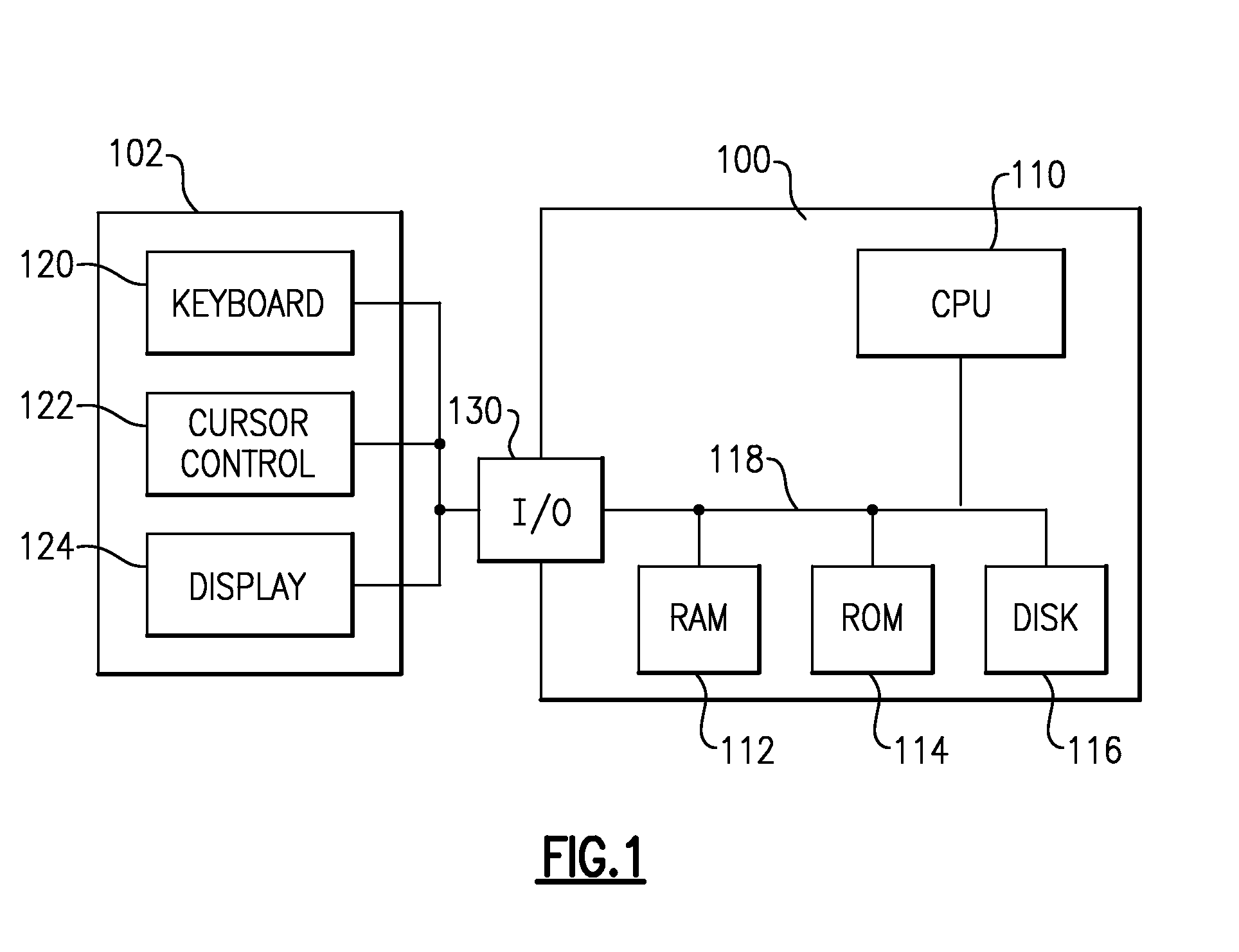
[0017]FIG. 1 is a block diagram illustrating an exemplary computer system of the type in which the present invention can be employed. The system includes a computer 100 connected to one or more external peripheral devices 102. The computer 100 includes a central processing unit 110, a main memory which is typically implemented in the form of a random access memory 112, a static memory that can comprise a read only memory 114 and a permanent storage device, such as a magnetic or optical disk 116.

[0018]The CPU 110 communicates with each of these forms of memory through an internal bus 118. The one or more peripheral devices 102 include, but are not limited to, a data entry device such as a keyboard 120, a cursor control device 122 such as a mouse, trackball, a pen and stylus, a touch-sensitive screen, a trackpad, a microphone, a joystick, a camera or the like, a display device 124 and, optionally, an audio device such as speakers (not shown). The display device 124, such as a CRT moni...


PUM


Abstract

A software package defines installation and assembly requirements for a product through simplified representations of a 3D design model having a multiple of component parts which define the product in a data format different than that which created the 3D design model. Data created by the process replaces documentation supplied by traditional installation and assembly drawings. Documentation of the installations and assemblies is accomplished entirely electronically.

Description

BACKGROUND OF THE INVENTION[0001]The present invention relates to a software package, and more particularly to a model based definition installation and assembly drawing system software which replaces documentation supplied by traditional installation and assembly release drawings to bridge product development with the creation of end user data.[0002]Product development involves a variety of software and data systems. Conventional product development systems often include a mechanical engineering and design CAD tool such as Pro / Engineer which is capable of creating complex 3D models, assemblies, and 2D measured drawings. A typical Pro / ENGINEER software package includes different modules customizable to a customer's specific requirements. Pro / ENGINEER outputs include solid model data for tooling, rapid prototyping, CNC manufacturing, and finite element analysis.[0003]Oftentimes, the full design model is proprietary or includes detailed information of a product unnecessary for later e...

Claims


Application Information

Patent Timeline
IPC IPC(8): G06F19/00
CPCG06F17/50G06F30/00
Inventor BOWLING, WILLIAM C.HANDLER, TOM
Owner ROCKETDYNE
Why Eureka
Try Eureka