
Nozzle seal slot measuring tool and method

Active Publication Date: 2007-05-03
GENERAL ELECTRIC CO
View PDF12 Cites 5 Cited by
  • Summary
  • Abstract
  • Description
  • Claims
  • Application Information

AI Technical Summary

Benefits of technology

[0008] In an exemplary embodiment of the invention, a tool for measuring seal slot position includes a tool shaft having a longitudinal axis, an eccentric pin sized to fit into a seal slot disposed at one end of the tool shaft, and a disk member disposed at an opposite end of the tool shaft. The disk member facilitates rotation of the tool shaft and pin in the seal slot. An exemplary seal slot suitable for the invention is a turbine nozzle seal slot.

Problems solved by technology

If the seal slot positions are not aligned between adjacent segments, it will not be possible to install the seals.
Service run nozzles in a gas turbine may have distorted sidewalls as a result of previous weld repairs or due to stress relief during service.
Creep strain due to applied loads at operating temperatures may also contribute to distortion.
This movement of the sidewalls will cause the seal slots that are contained within the sidewalls to be out of position relative to engine center.
If the sidewalls are not pressed back into position, the seal slots between adjacent segments would not be aligned with each other, and it may prove impossible to fit the seals in place.
This will result in compressor discharge air leaking directly into the hot gas path and will reduce the amount of air available for combustion and for cooling of the nozzle.
The result of reduced air for combustion will be lower performance of the turbine and increased emissions.
A reduction in available cooling air will result in increased oxidation of the nozzle due to a resultant higher metal temperature and the lack of cooling will also cause changes to thermal gradients within the nozzle leading to increased cracking of the part.
This will increase subsequent repair costs and may reduce the life of the parts.
Misaligned sidewalls may also result in flow path steps.
The hot gas will not have a smooth path but will be tripped by the mismatch between adjacent nozzle segments, resulting in turbulent flow and reduced energy of the gas stream, thereby reducing engine performance.
Turbulent flow also increases thermal transfer to the nozzle and so will raise the metal temperature, leading to increased oxidation and cracking.

Method used


Image

  • Nozzle seal slot measuring tool and method
  • Nozzle seal slot measuring tool and method
  • Nozzle seal slot measuring tool and method

Examples


Embodiment Construction

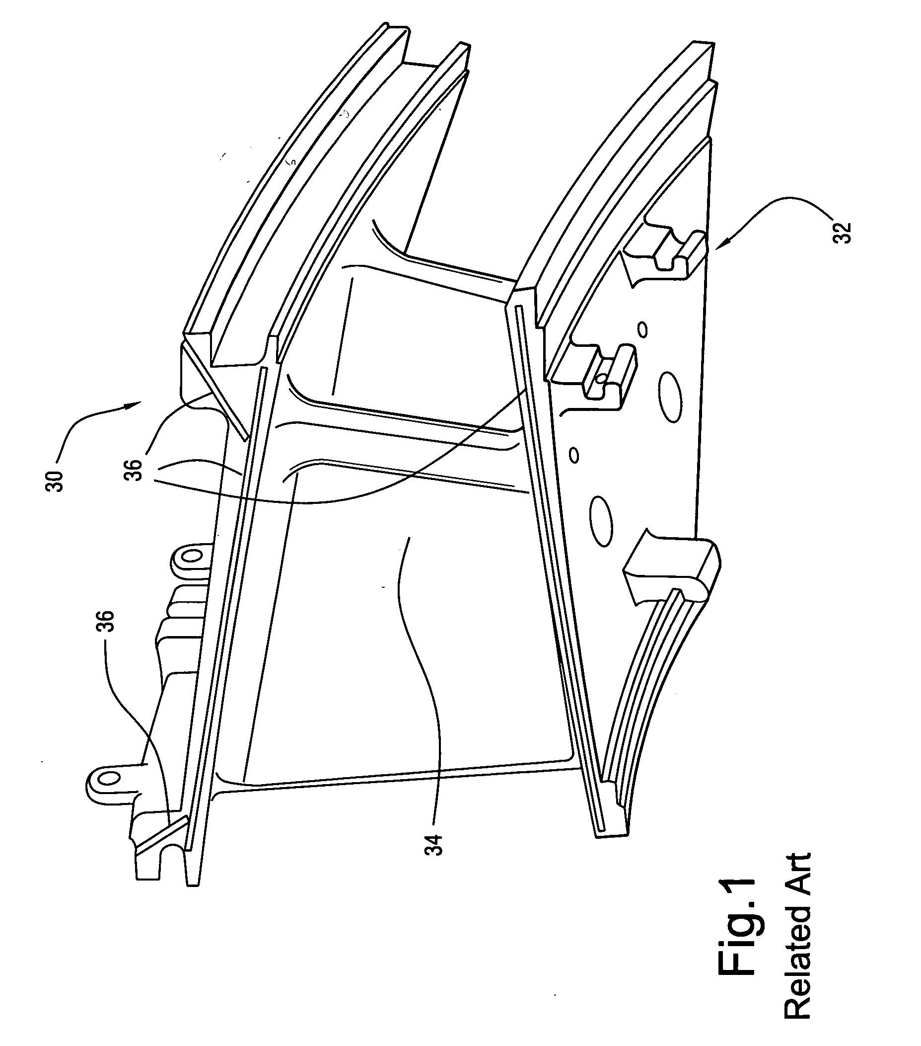
[0014]FIG. 1 is a perspective view of a gas turbine nozzle section. Generally, the section includes an outer wall 30, an inner wall 32, and an airfoil 34 therebetween. The section also includes a number of seal slots 36. The seal slots 36 exist to retain the end face seals (sometimes referred to as spline seals or slash face seals) that seal between adjacent nozzle segments and prevent the ingestion of compressor discharge air into the gas path.

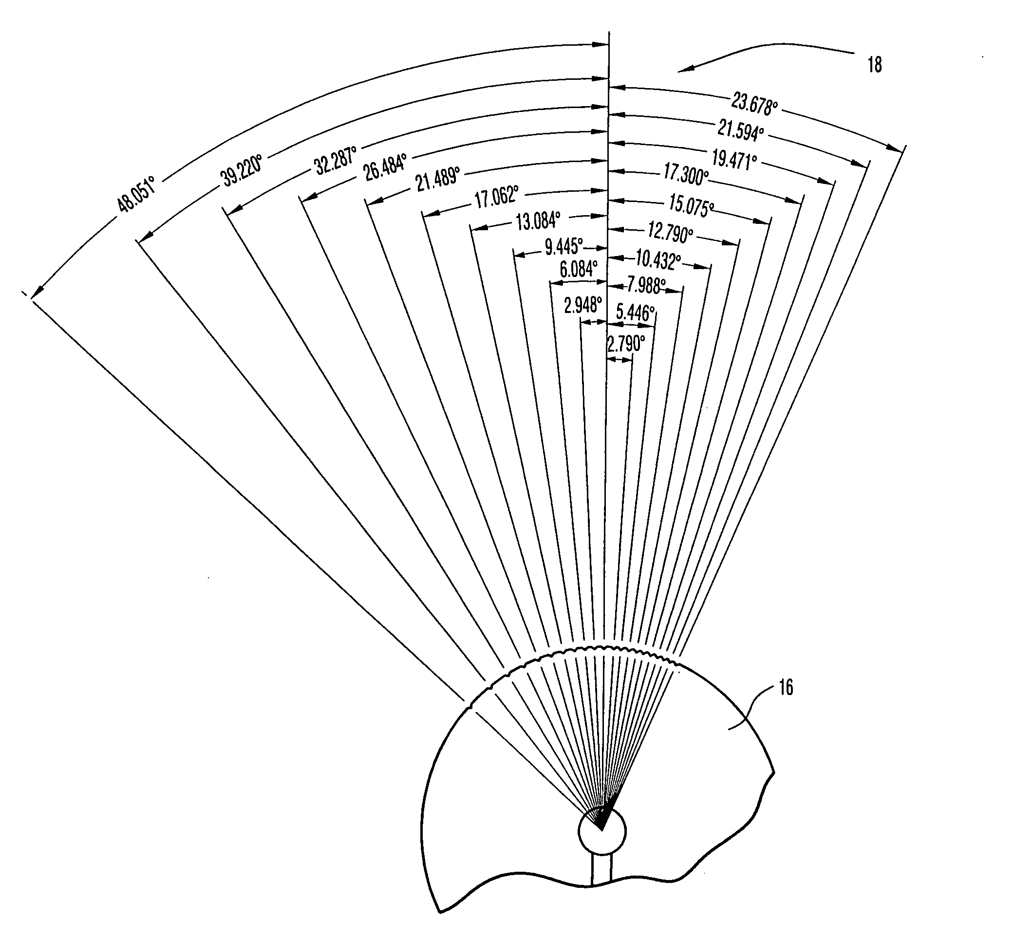
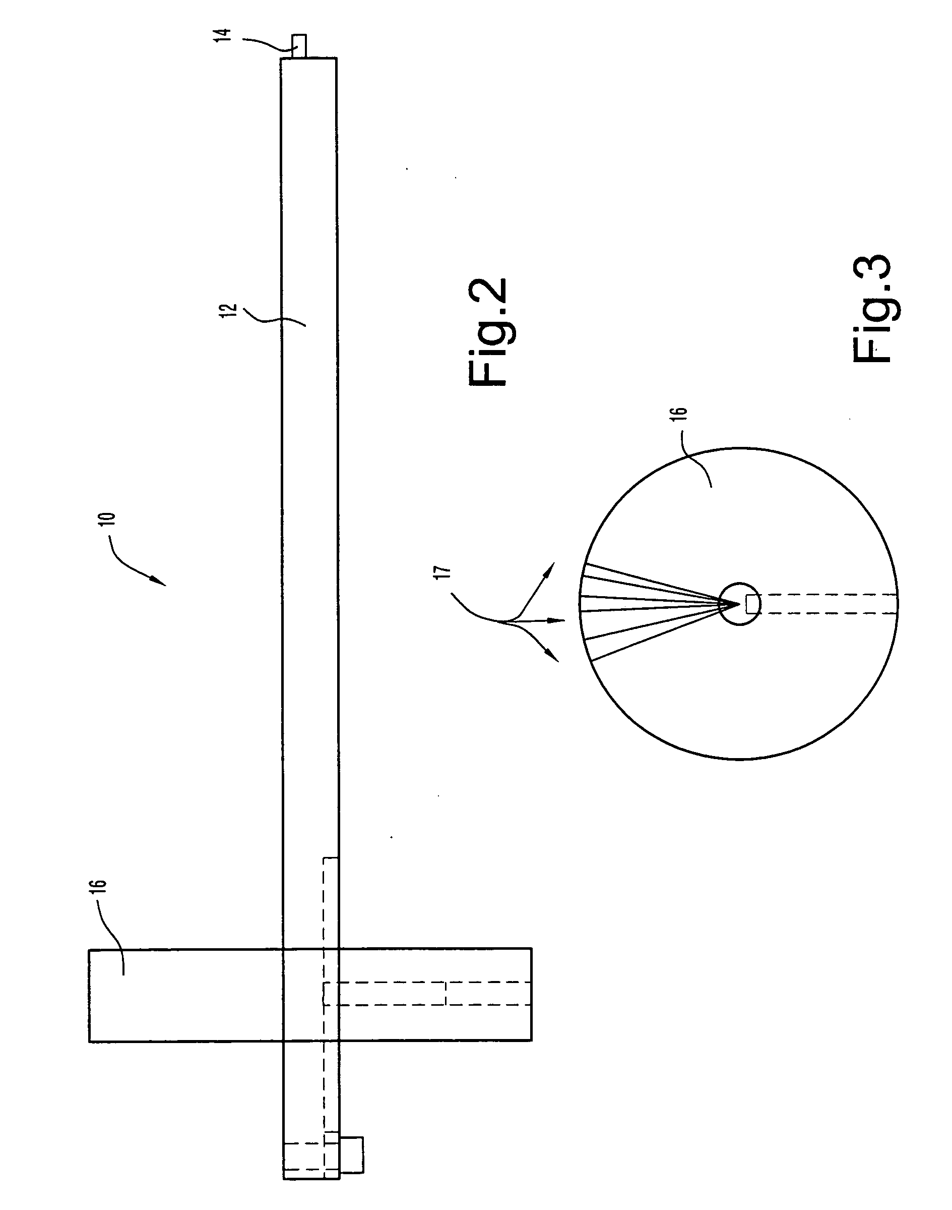
[0015]FIGS. 2-4 illustrate the tool of the invention for measuring turbine nozzle seal slot position. The tool 10 includes a tool shaft 12 having a longitudinal axis. A pin 14 such as a hardened dowel pin or the like is disposed at one end of the tool shaft 12 and is eccentric relative to the longitudinal axis. The pin 14 may be machined from the shaft 12 or may be brazed to the shaft and finish machined into the final product. The pin 14 is sized appropriately to fit into a turbine nozzle seal slot. For example, a width of the pin is genera...


PUM


Abstract

A tool for measuring seal slot position includes a tool shaft having a longitudinal axis, a pin eccentrically disposed at one end of the tool shaft relative to the longitudinal axis, and a disk member disposed at an opposite end of the tool shaft that facilitates rotation of the tool shaft and pin in the seal slot. The tool provides for increased accuracy in measuring seal slot position such as turbine nozzle seal slot position.

Description

CROSS-REFERENCES TO RELATED APPLICATIONS [0001] (Not Applicable) STATEMENT REGARDING FEDERALLY SPONSORED RESEARCH OR DEVELOPMENT [0002] (Not Applicable) BACKGROUND OF THE INVENTION [0003] The present invention relates to a nozzle seal slot tool and method and, more particularly, to a nozzle seal slot tool including a continuous measurement pin capable of providing continuous measurement data and having a readable scale. [0004] It is desirable to control the position of seal slots within drawing dimensions because the seals fit within the slots of adjacent nozzle segments. If the seal slot positions are not aligned between adjacent segments, it will not be possible to install the seals. Service run nozzles in a gas turbine may have distorted sidewalls as a result of previous weld repairs or due to stress relief during service. Creep strain due to applied loads at operating temperatures may also contribute to distortion. This movement of the sidewalls will cause the seal slots that ar...

Claims


Application Information

Patent Timeline
IPC IPC(8): G01B5/00
CPCF01D9/041F01D11/00G01B3/56Y10S33/08
Inventor SHERLOCK, GRAHAM DAVIDKALMAR, PAUL LAWRENCETHOMPSON, CHRISTOPHER EDWARD
Owner GENERAL ELECTRIC CO
Features
  • Generate Ideas
  • Intellectual Property
  • Life Sciences
  • Materials
  • Tech Scout
  • Unparalleled Data Quality
  • Higher Quality Content
  • 60% Fewer Hallucinations
Learn More