Roof vents

Inactive Publication Date: 2007-05-03
GALEAZZO JOHN P +1
View PDF42 Cites 36 Cited by
  • Summary
  • Abstract
  • Description
  • Claims
  • Application Information

AI Technical Summary

Benefits of technology

[0004] Accordingly, it is an aspect of the present invention t

Problems solved by technology

Building structures can be damaged by moisture trapped within areas of the building.
Current roof vent designs, however, may trap outside debris and / or permit passage of debris to areas underlying the roof deck.
Trapped debris may interfere with roof vent performance and / or may be difficult to remove from the roof vent.
Moreover, debris passing through the roof vent can contaminate areas underlying the roof deck.

Method used


Image

  • Roof vents
  • Roof vents
  • Roof vents

Examples


Embodiment Construction

[0015] Certain terminology is used herein for convenience only and is not to be taken as a limitation on the present invention. Further, in the drawings, the same reference numerals are employed for designating the same elements.

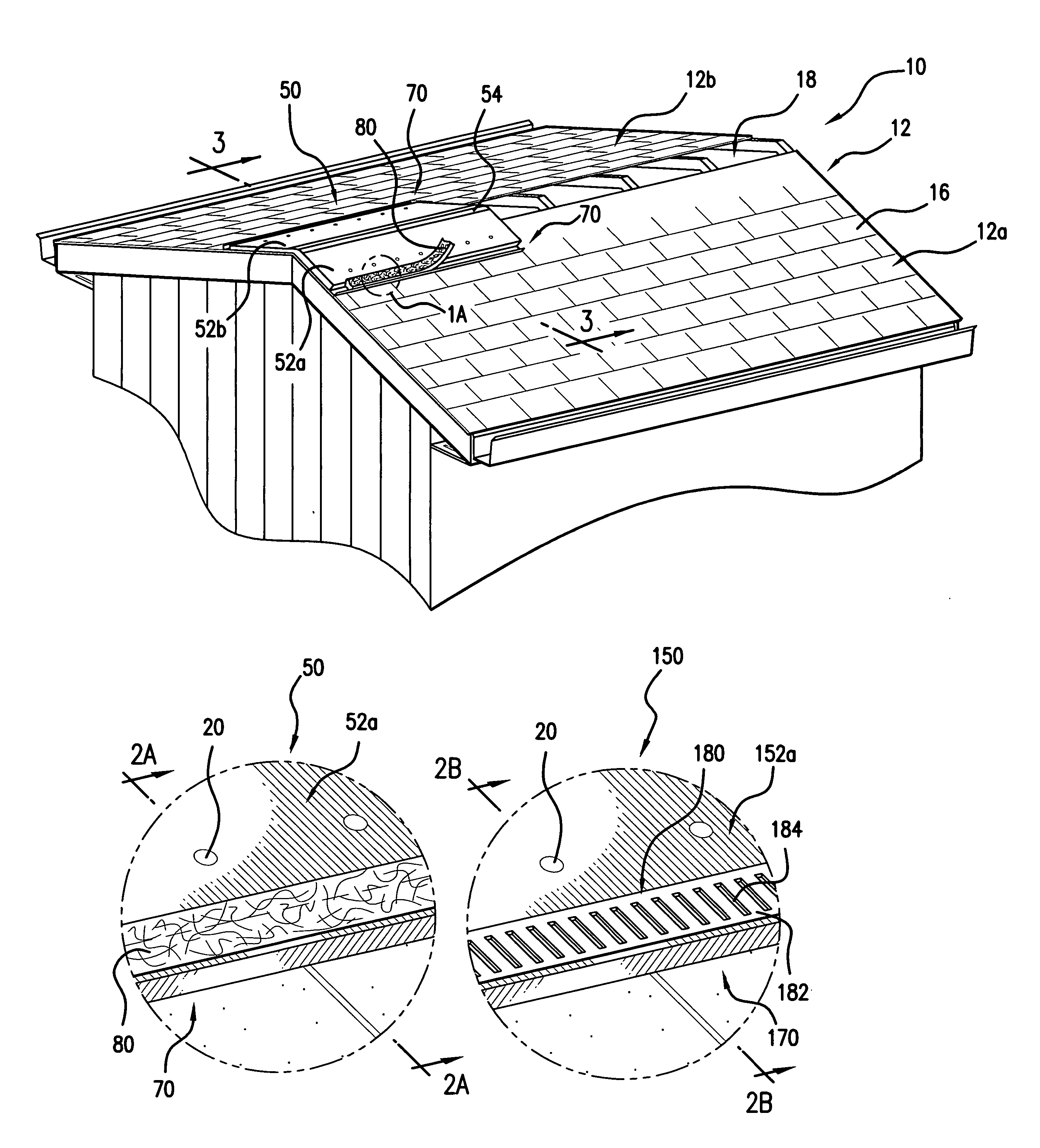
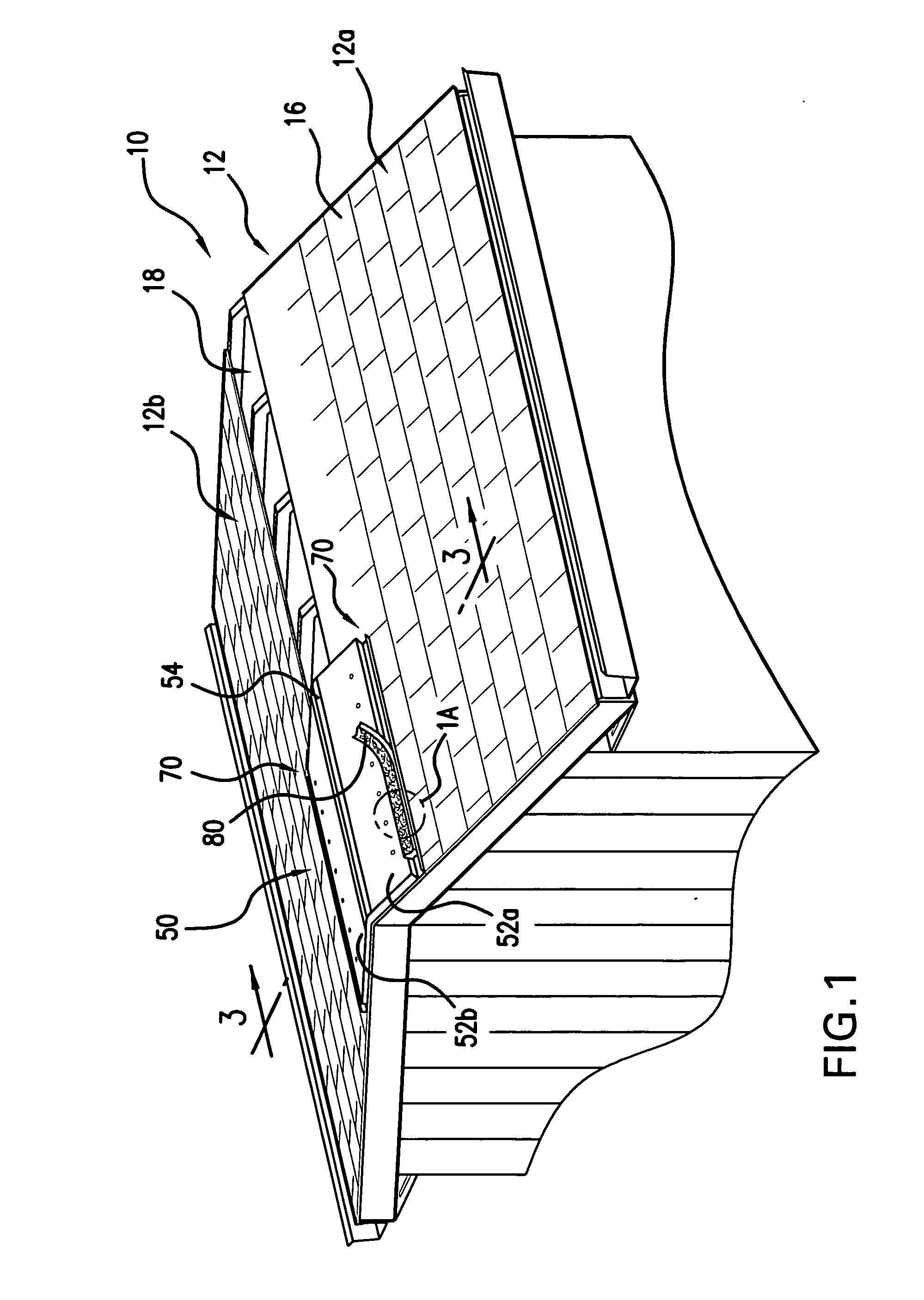
[0016]FIG. 1 depicts an example of one or more roof vents being attached to a roof deck to form a roof incorporating aspects of the present invention. Roof vents described throughout this application may be used with a wide range of roof designs. For instance, roof vents may be used with various gabled or hipped roof designs. Roof vents can also be used with gambrel, saltbox, mansard, shed, flat or other roof designs. Roof vents can also be provided at or near the junction between a portion of the roof and an adjacent structure. For instance, roof vents can be provided at or near the junction between a portion of the roof and a vertical wall. FIG. 1 illustrates a roof vent 50 being attached to a gabled roof 10 with a roof deck 12 having two sloped roof deck...


PUM


Abstract

Roof vents are configured to cover a ventilation opening formed in a roof deck. Roof vents can permit venting of an area underlying the roof deck while shielding the ventilation opening from condensation such as rain. Roof vents can also include a guard for shielding a ventilation area from outside debris.

Description

FIELD OF THE INVENTION [0001] The present invention relates to venting devices, and more particularly, to roof vents. BACKGROUND OF THE INVENTION [0002] Building structures can be damaged by moisture trapped within areas of the building. For example, trapped condensation may encourage mold formation and / or promote rotting, rusting, buckling, paint peeling or other deterioration of building frame components. It is known to provide roof vents to help vent moisture that might otherwise damage building structures. Known roof vents are positioned over ventilation openings in a roof deck to permit venting of an area underlying the roof deck while shielding the ventilation opening from condensation such as rain. [0003] Current roof vent designs, however, may trap outside debris and / or permit passage of debris to areas underlying the roof deck. Trapped debris may interfere with roof vent performance and / or may be difficult to remove from the roof vent. Moreover, debris passing through the r...

Claims


Application Information

Patent Timeline
IPC IPC(8): E04B7/00E04H12/28F24F7/02
CPCE04D13/174F24F7/02
Inventor GALEAZZO, JOHN P.GALEAZZO, STEPHEN J.
Owner GALEAZZO JOHN P
Why Eureka
Try Eureka