Sandwich molding system with independent runner passages
- Summary
- Abstract
- Description
- Claims
- Application Information
AI Technical Summary
Benefits of technology
Problems solved by technology
Method used
Image

Examples
first embodiment
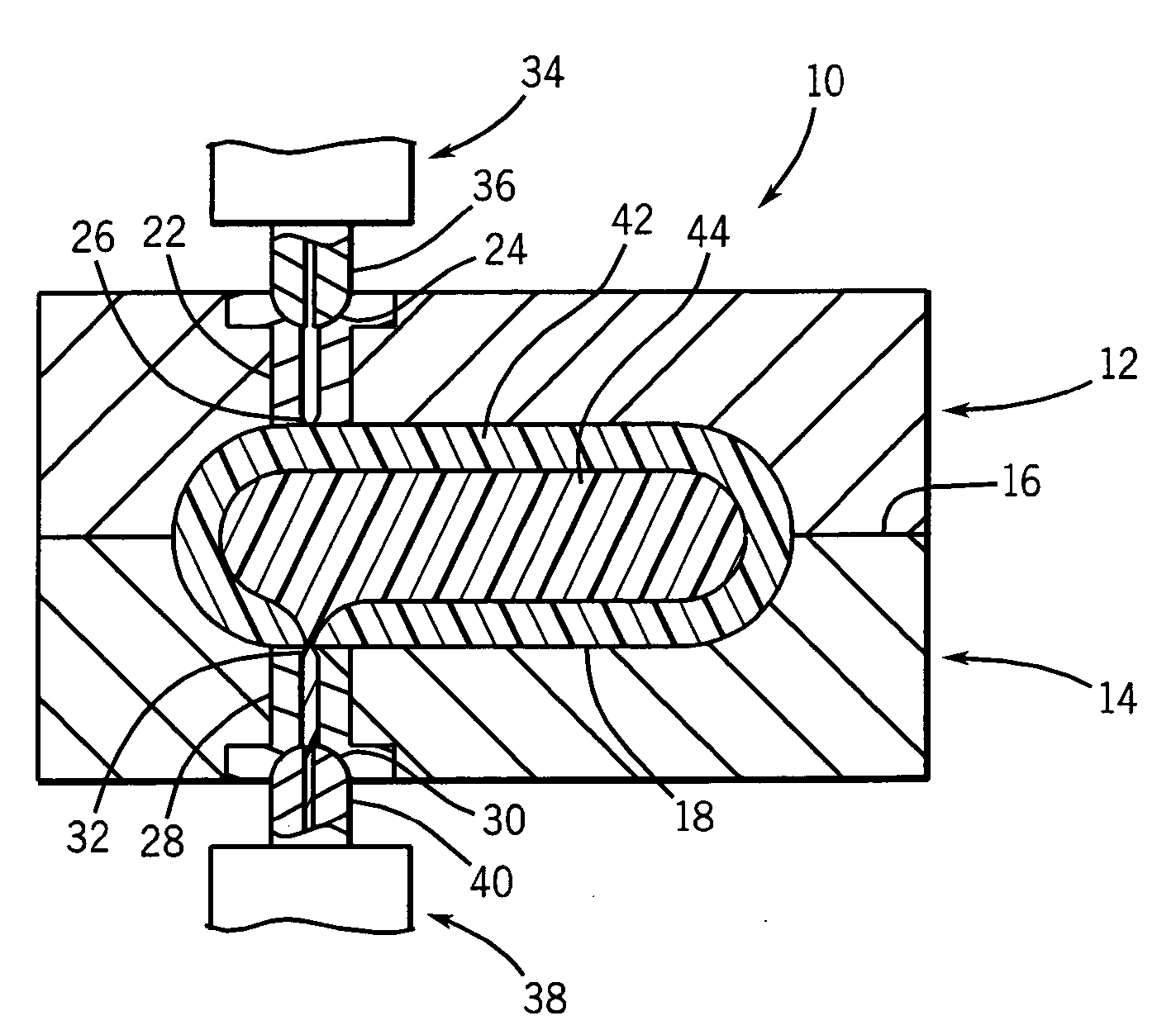
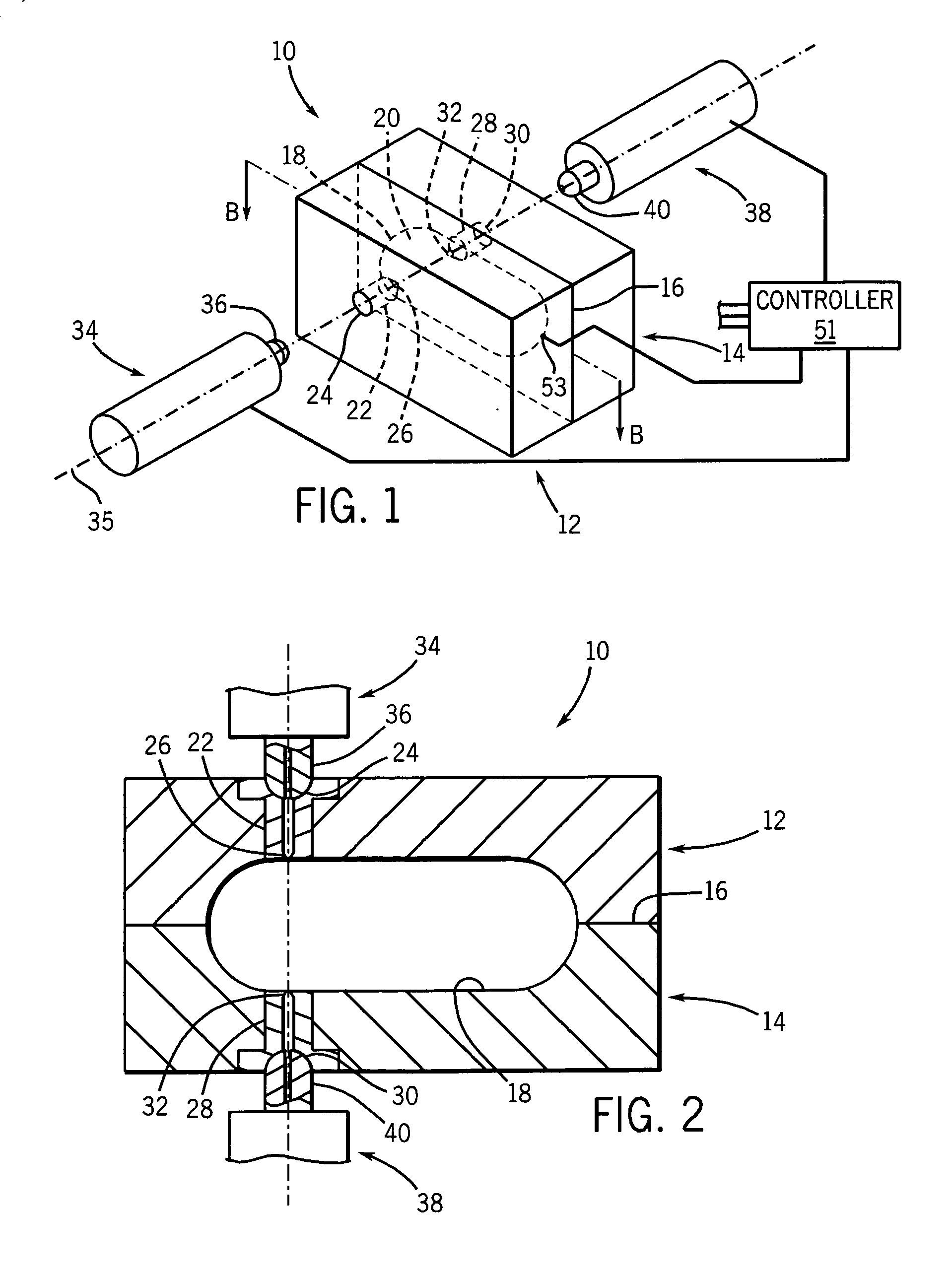
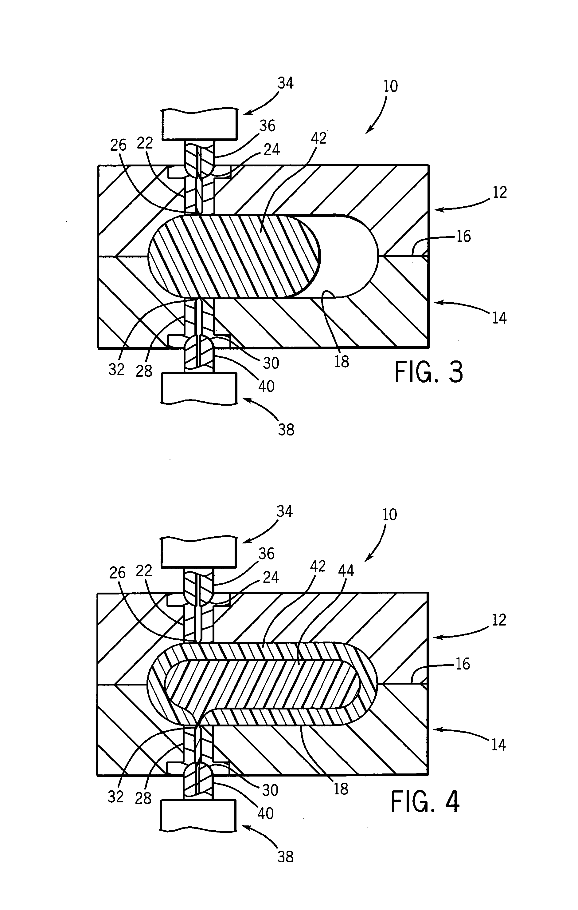
[0037] A first injector 34, extending along axis 35, has a first machine nozzle tip 36 which can be placed against the first inlet 24 of the first sprue bushing 22. A second injector 38, also extending along axis 35, has a second machine nozzle tip 40 which can be placed against the second inlet 30 of the second sprue bushing 28. Once placed against the first and second inlets 24 and 30, the first and second injection nozzle tips 36 and 40 may inject thermoplastic material through the sprue bushings 22 and 28 to fill the mold cavity 18. In this first embodiment, the sprue bushings 22 and 28, the inlets 24 and 30, the gates 26 and 32, the injectors 34 and 38, and the injection nozzle tips 36 and 40 all extend along the axis 35, but it is not required that any of these elements be coaxial.
[0038] Referring now to FIG. 2, during a first step of the sandwich molding process, the mold portions 12 and 14 close along the parting line 16 to provide the mold cavity 18, and the first machine n...
second embodiment
[0043] Referring now to FIG. 5, in the invention, the mold portions 12 and 14 join along a parting line 16 to provide a plurality of mold cavities 18a, 18b, 18c and 18d. Hot runner manifolds 50 and 52 are held to the opposed outer faces of the mold portions 12 and 14 by clamp plates 54 and 56, respectively. The hot runner manifolds receive the nozzles tips 36 and 40 and provide balanced runners 60 and 62 branching to each of eight sprue bushings 22a-22d (for balanced runner 60) and 30a-30d (for balanced runner 62). Balanced runners provide identical flow resistance from the inlet at nozzle tips 36 and 40 to each of the cavities 18a-18b to provide comparable flow of thermoplastic along each branch.
[0044] The balanced runners 60 and 62 add complexity to the mold, but are still far simpler than would be required of conventional runner passages used for sandwich molding in which a common channel must handle two different materials from two different injectors. The simplicity and symmetr...
PUM
| Property | Measurement | Unit |
|---|---|---|
| Fraction | aaaaa | aaaaa |
| Fraction | aaaaa | aaaaa |
| Temperature | aaaaa | aaaaa |
Abstract
Description
Claims
Application Information