Recording media processing device and image forming device

a recording media and processing device technology, applied in the field of recording media, can solve the problems of reducing the productivity of the recording media processing device, not being able to feed the next, and the edge of the recording media touching the transport roller b>103/b>, and causing jamming

Active Publication Date: 2007-05-03
KYOCERA DOCUMENT SOLUTIONS INC
View PDF2 Cites 4 Cited by
  • Summary
  • Abstract
  • Description
  • Claims
  • Application Information

AI Technical Summary

Benefits of technology

[0012] According to the present invention, a first branching pawl is disposed on the transport path for switching the direction of transport of the recording media between the transport path and the processing unit; a second branching pawl is disposed beyond the first branching pawl on the transport path for switching the direction of transport of the recording media between the output tray and the shunting roller; a transport roller is provided in the direction of transport between the first and second branching pawls; and cutaways are formed in the first and second branching pawls so as not to interfere with the transport roller, the transport roller and the first and second branching pawls being disposed so as to overlap when seen from the side, whereby the direction of transport of the recording media can be switched smoothly by the first and second branching pawls.

Problems solved by technology

Thus, when the stack of recording media undergoes staple processing, edge stapling or center stapling is performed by the stapler, but while staple processing is being performed in the processing tray, it is not possible to feed the next stack of recording media into the processing tray, and it is therefore necessary to provide a pause in the transport of the recording media during staple processing.
However, this reduces the productivity of the recording media processing device.
Furthermore, the prior art presents such problems as those wherein, when the recording media is transported to the stapling unit (not shown in the drawing), the transport roller 103 rotates in reverse, as a result of which, there is a risk of the edge of the recording media touching the transport roller 103 and jamming.

Method used


Image

  • Recording media processing device and image forming device
  • Recording media processing device and image forming device
  • Recording media processing device and image forming device

Examples


Embodiment Construction

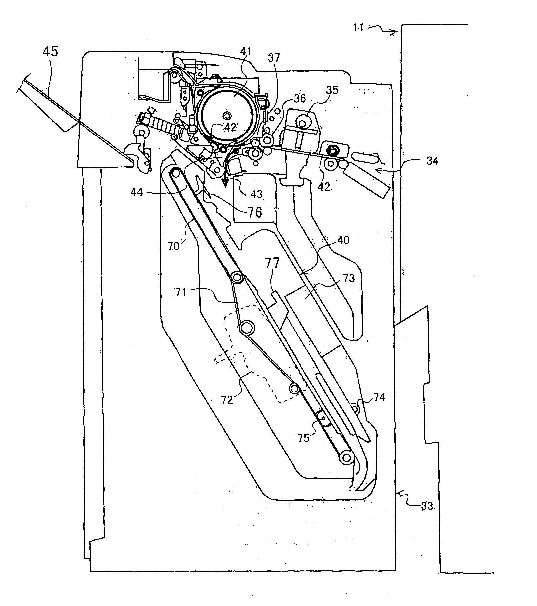
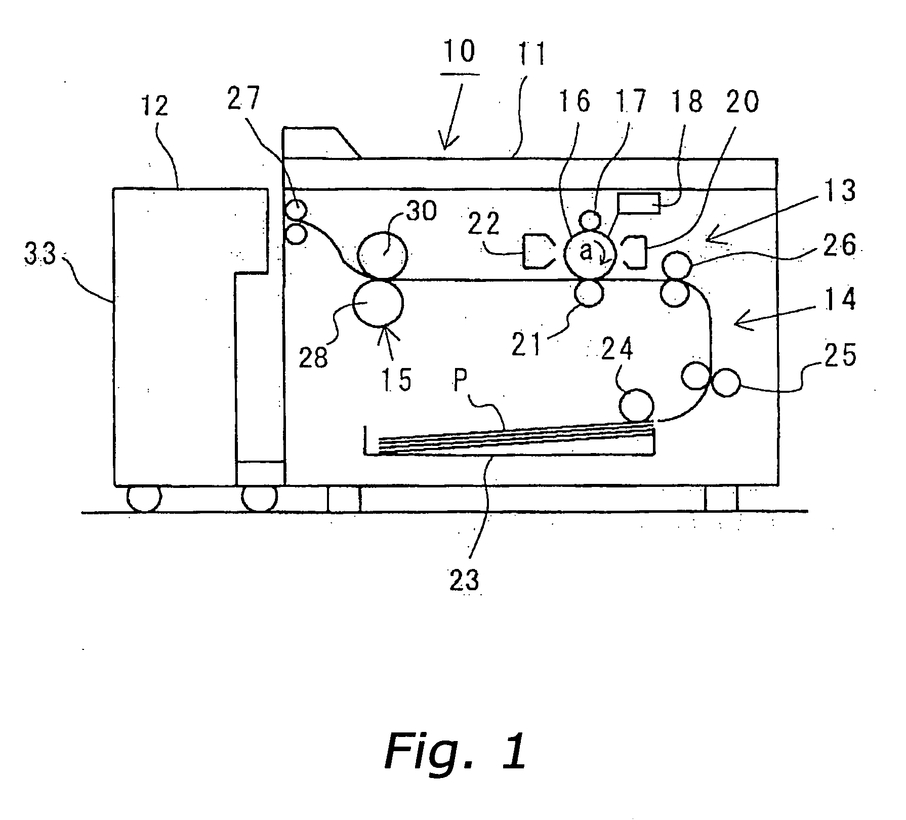
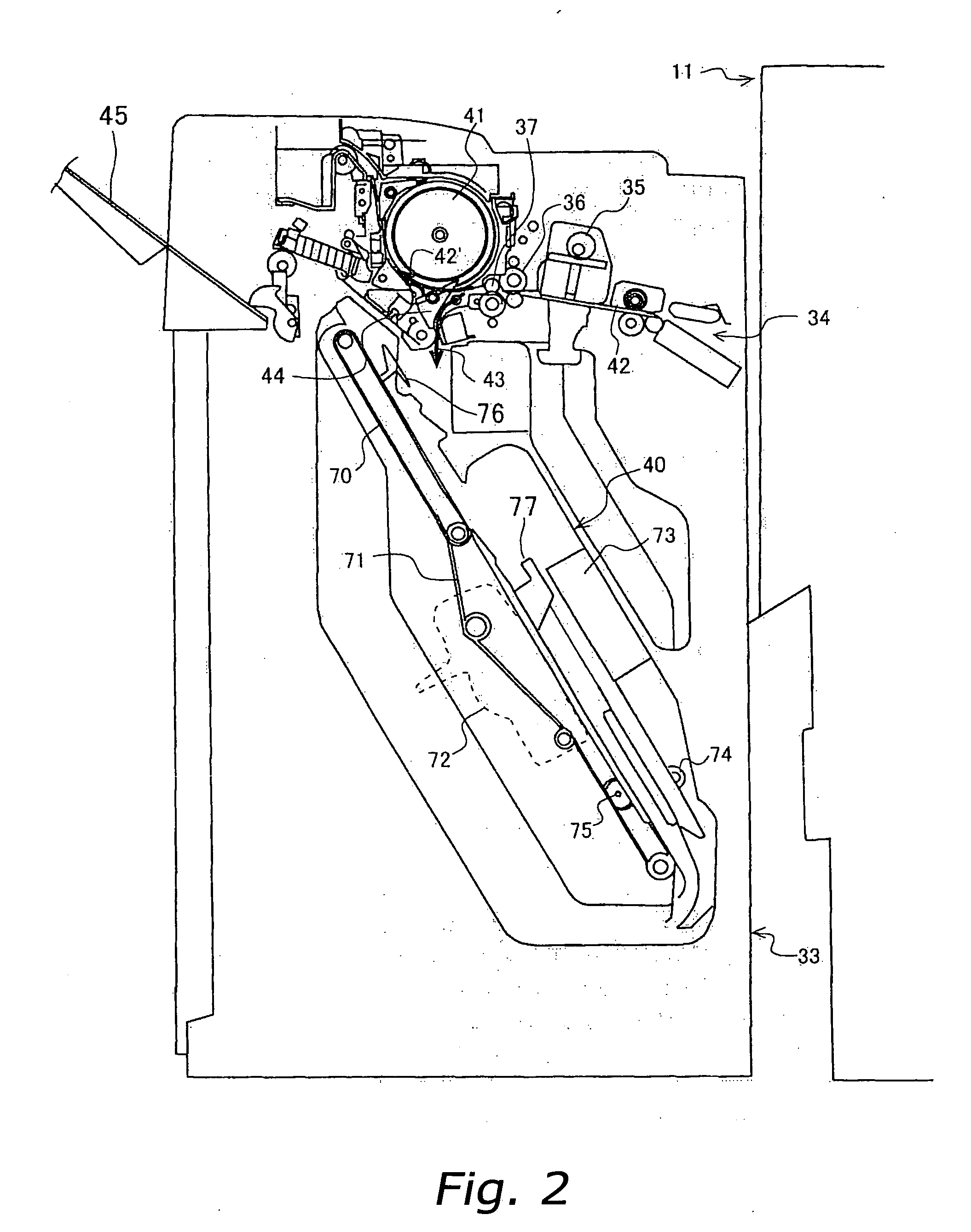
[0019] Hereinafter a mode of embodiment of the image forming device according to the present invention is described with reference to the drawings.

[0020]FIG. 1 illustrates one example of an image processing device according to the present mode of embodiment. The figure is a longitudinal sectional view schematically illustrating the constitution of the image forming device in a simplified manner. An image forming device 10 comprises an image forming device main body 11 and a recording media processing device 12. This recording media processing device 12 is disposed adjacent to the image forming device main body 11.

[0021] Note that, in the present mode of embodiment, the image forming device 10 described is of the electrophotographic type and the recording media processing device 12 described comprises a stapler, but the image forming device and the recording media processing device according to the present invention are not limited to such devices.

[0022] Hereinafter the constituti...


PUM

PropertyMeasurementUnit
outer circumferenceaaaaaaaaaa
circumferenceaaaaaaaaaa
lengthaaaaaaaaaa

Abstract

The present invention comprises a shunting roller 41, and when recording media P, which is output from an image forming device main body 11, is stacked as a stack of recording media and staple processing is performed thereon, the shunting roller 41 rotates so as to receive subsequent recording media P in the wrapping direction thereof, while the first stack of recording media undergoes staple processing. The present invention also comprises a first branching pawl 44, for switching the direction of transport of recording media P between a transport path 42 and a processing unit 40, and a second branching pawl 47, for switching it between an output tray 45 and the shunting roller 41. Furthermore, a transport roller 53 for transporting the recording media P, is provided in the direction of transport between the first and second branching pawls 44 and 47, and cutaways 57 and 58 are formed in the first and second branching pawls 44 and 47 so as not to interfere with this transport roller 53, the transport roller 53 and the first and second branching pawls 44 and 47 being disposed so as to overlap when seen from the side.

Description

FIELD OF THE INVENTION [0001] The present invention relates to a recording media processing device disposed adjacent to an image forming device main body, and serving to perform after-processing such as punch processing and staple processing on recording media on which images have been formed, and to an image forming device such as a copier, a printer or a fax machine equipped with the same. BACKGROUND INFORMATION [0002] Conventionally, recording media processing devices are known which are disposed adjacent to the main body of an image forming device such as a copier or a printer and serve, for example, to perform after-processing (such as punch processing, staple processing and other binding processing) on recording media on which an image has been formed. These recording media processing devices perform staple processing (binding operation) and the like on recording media that has been output from the image forming device main body and stacked on a processing tray after passing t...

Claims


Application Information

Patent Timeline
Patent Type & Authority Applications(United States)
IPC IPC(8): B65H39/00
CPCB65H29/12B65H29/51B65H29/58B65H2301/4213B65H2404/1531B65H2404/632B65H2801/06B65H2220/09
Inventor OKUMURA, KEIJI
Owner KYOCERA DOCUMENT SOLUTIONS INC
Why Eureka
Try Eureka