Indirect power-linking device

a power-linking device and power-linking technology, which is applied in the direction of mechanical energy handling, mechanical equipment, machines/engines, etc., can solve problems such as suppressive effect, achieve fast and efficient cooling effect, facilitate fan heat dissipation, and power operation

Inactive Publication Date: 2007-05-03
SUNONWEALTH ELECTRIC MACHINE IND
View PDF1 Cites 5 Cited by
  • Summary
  • Abstract
  • Description
  • Claims
  • Application Information

AI Technical Summary

Benefits of technology

[0008] If the power-device pertains to the preferred embodiment of a rotor of a cooling fan and the power-driven device pertains to the preferred embodiment of a cooling liquid agitator, the agitator generates a powerful operation arising from the torque formed by the suppressive effect of the magnetic field lines and the indirect magnetic traction of the rotor, so as to agitate the cooling liquid. The cooling liquid absorbing heat becomes a dynamic hot liquid that uniformly diffuses and conducts the heat to each cooling fin to facilitate the heat dissipation of the fan, achieving a faster and more efficient cooling effect.

Problems solved by technology

Consequently, when the power device rotates, the magnetic field lines between the magnets of the power-driving device and the power-driven device are distorted to result in the suppressive effect, further forming a rotational torque to drive and synchronously rotate the power-driven device as a result of the magnetic traction of the power device.

Method used


Image

  • Indirect power-linking device
  • Indirect power-linking device
  • Indirect power-linking device

Examples


Embodiment Construction

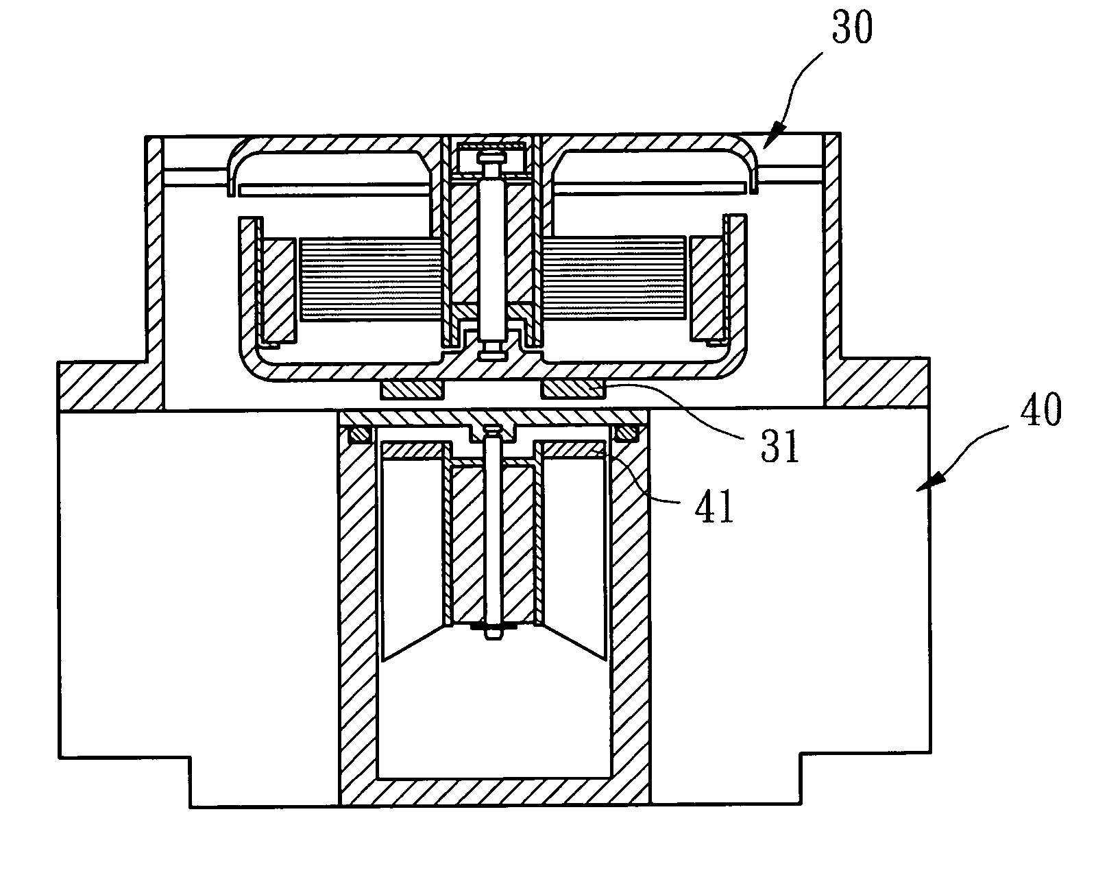
[0014] The invention relates to an indirect power-linking device, which has magnets disposed respectively at the locations where corresponds to a power-driving device and a power-driven device mutually drag. The magnets disposed respectively at the power-driving device and the power-driven device all have at least two magnetic poles so as to make the power-driving device and the power-driven device operate synchronously and generate powerful operation, achieving the optimal cooling effect.

[0015] Listed below are several preferred embodiments depicting the respective position of each part in the present invention.

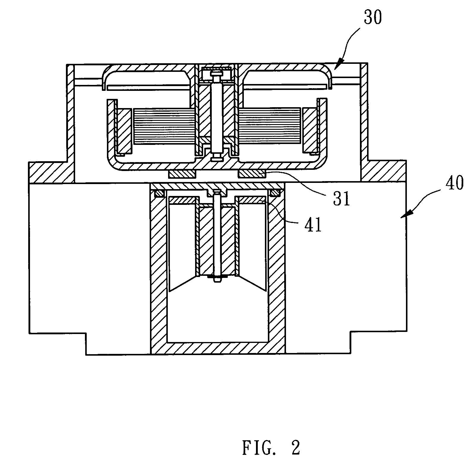
[0016] Please also refer to FIG. 2 and FIG. 3 containing a power-driving device 30 and a power-driven device 40, wherein the magnets 31, 41 are disposed at the locations where corresponds to the power-driving device 30 and the power-driven device 40 mutually dragging, and all have at least two magnetic poles, e.g. N pole and S pole. The magnets 31, 41 may take a form of a ...


PUM


Abstract

The invention relates to an indirect power-linking device, which are disposed respectively the magnets at the locations where correspond to a power-driving device and a power-driven device that mutually attract. The magnets shall have at least one N pole and one pole. Therefore, when the power-driving device rotates, the magnetic field lines between the magnets of the power-driving device and the power-driven device are distorted to generate a suppressive effect in formation of a rotational torque. The rotational torque can drive the power-driven device and the power-driving device to generate a synchronous and powerful operation.

Description

FIELD OF THE INVENTION [0001] The invention relates to an indirect power-linking device, which is applied to the indirect power transmission between a power-driving device and a power-driven device so that the power-driven device generates a powerful operation driven by the traction of the power-driving device. BACKGROUND OF THE INVENTION [0002] As shown in FIG. 1, Taiwan Patent Application No. 94130223 discloses a cooling device. The cooling device includes a cooling fan 50 and a heat sink 21. The heat sink 21 directly contacts with a heating element 81 to absorb the heat therefrom. The cooling fan 50 is disposed on the heat sink 21 to dissipate heat. [0003] The heat sink 21 contains a central heat conducting body 22. A plurality of cooling fins 23 extend from the periphery of the central heat conducting body 22. The central heat conducting body 22 has an absolutely sealed and hollow chamber 221 therein. The chamber 221 is filled with a cooling liquid and disposed an agitator 25. T...

Claims


Application Information

Patent Timeline
Patent Type & Authority Applications(United States)
IPC IPC(8): H01H9/00
CPCF01P7/084F04D25/0613H02K7/14H02K16/02H02K49/108F04D13/027
Inventor HONG, ALEXMIYAHARA, MASAHARU
Owner SUNONWEALTH ELECTRIC MACHINE IND
Why Eureka
Try Eureka