Image stabilizer, and image shake correction method for imaging device

a technology of image stabilizer and imaging device, which is applied in the field of image stabilizer, can solve the problems of difficult miniaturization of image stabilizer and undesirable increase in optical device size, and achieve the effect of reliable correction of image shak

Inactive Publication Date: 2007-05-03
HOYA CORP
View PDF3 Cites 37 Cited by
  • Summary
  • Abstract
  • Description
  • Claims
  • Application Information

AI Technical Summary

Benefits of technology

[0005] The present invention provides a compact image stabilizer which is configured to be capable of reliably correcting image shake even if the magnification is large. The present invention further provides a method of correcting image shake by which image shake can be corrected reliably using a compact image stabilizer even if the magnification of the optical system thereof is large.
[0009] It is desirable for the moving range controller to operate so as to increase the moving range of the shake correction optical element as the optical focal length of the optical zoom device increases.
[0021] According to the image stabilizer and the method of correcting image shake to which the present invention is applied, a compact image stabilizer can reliably correct image shake even if the magnification of the optical system thereof is large.

Problems solved by technology

Since the operating range of the movable part of the optical system must be made to remain within a range in which image quality does not deteriorate (in which a sufficient amount of marginal rays is collected to prevent vignetting from occurring), the effective aperture of the lens must be increased to achieve a wide operating range, which undesirably increases the size of the optical device.
Additionally, since a long focal-length optical system has a large magnification, the amount of shake correction per unit of shake angle becomes great, which makes it difficult to miniaturize the image stabilizer.

Method used


Image

  • Image stabilizer, and image shake correction method for imaging device
  • Image stabilizer, and image shake correction method for imaging device
  • Image stabilizer, and image shake correction method for imaging device

Examples


Embodiment Construction

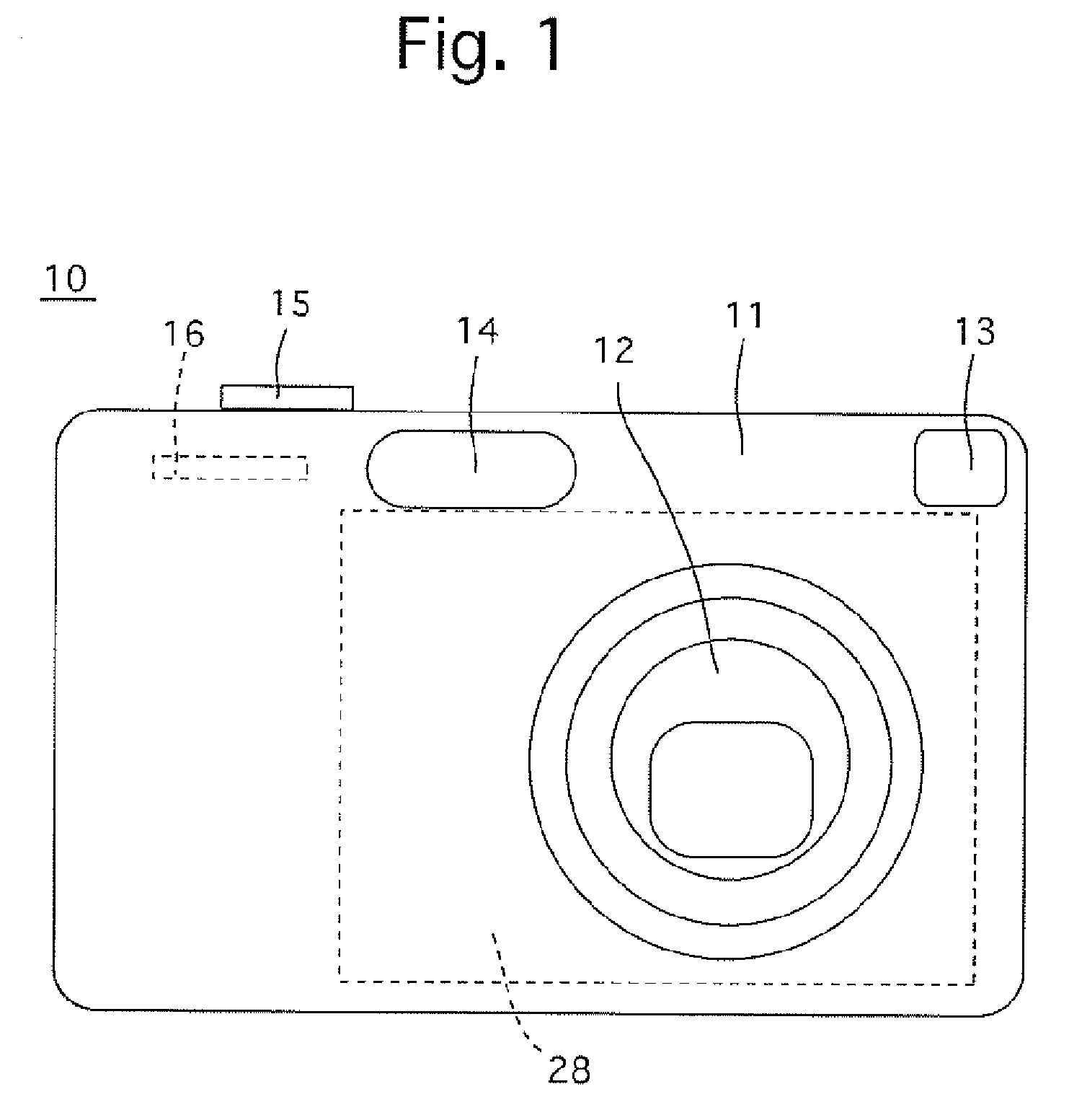
[0032]FIG. 1 shows a first embodiment of a digital camera (imaging device) 10 equipped with an optical axis correction apparatus according to the present invention. The digital camera 10 is provided on the front of a camera body 11 with a zoom lens (zoom lens barrel) 12, an optical viewfinder 13 and a flash 14. The digital camera 10 is provided on the top of the camera body 11 with a shutter release button 15. The digital camera 10 is provided on the back thereof with a zoom switch 16 and an LCD 28 which indicates the picture area (object coverage area).

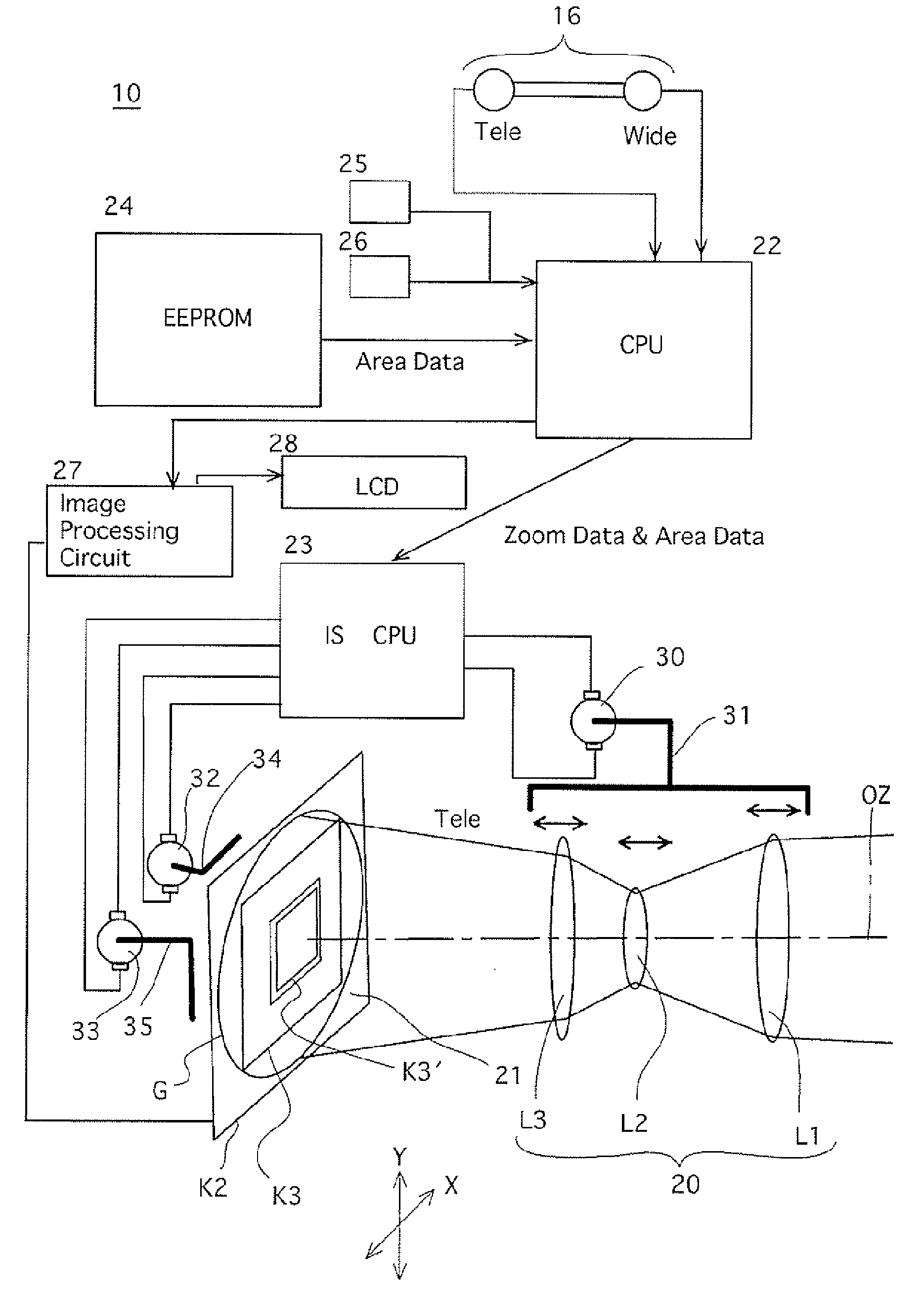
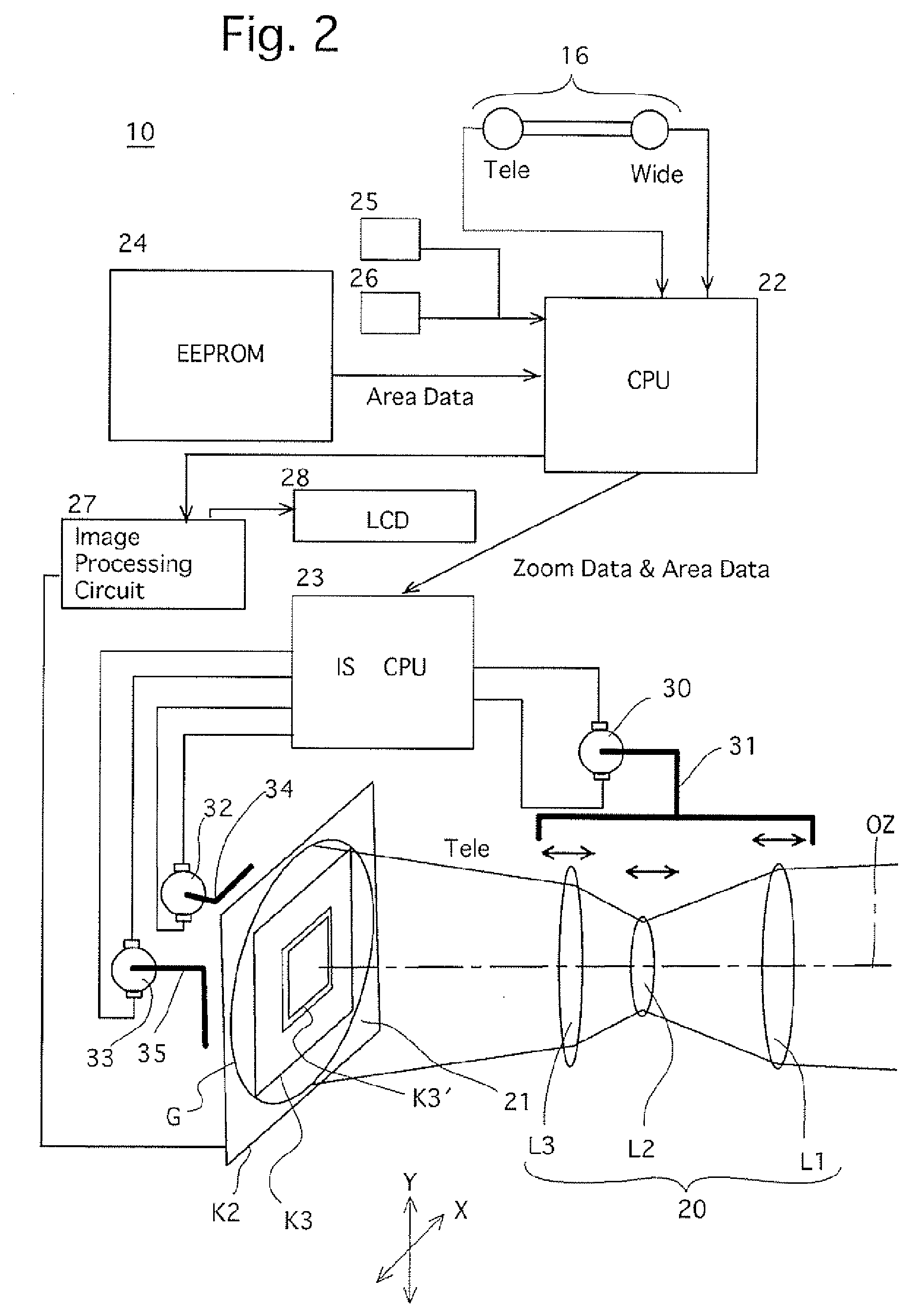
[0033] As shown in FIG. 2, the zoom lens 12 is provided with a zoom lens system (photographing optical system) 20 including a plurality of lens groups (first, second and third lens groups) L1, L2 and L3, and an image sensor (shake correction optical element) 21 which is located at a focal point of the zoom lens system 20. The optical axis of the zoom lens system 20 is shown by the letters “OZ” in FIG. 2. The digital camera 10 is pro...


PUM


Abstract

An image stabilizer includes an imaging device including an object coverage area changing device for changing an object coverage area, and an image sensor; an image shake correction device which moves a shake correction optical element of the imaging optical system in a plane orthogonal to an optical axis in accordance with a direction and magnitude of vibration applied to the image sensor; a memory, in which area data is prestored, the area data designating changes in relative sizes between an image circle of the imaging optical system and an effective picture area of an imaging surface of the image sensor; and a moving range controller which changes a moving range of the shake correction optical element that corresponds to a change of the object coverage area in accordance with an operating state of the object coverage area changing device based on the area data.

Description

BACKGROUND OF THE INVENTION [0001] 1. Field of the Invention [0002] The present invention relates to an image stabilizer, and further relates to a method of correcting image shake in an imaging device by moving a part of an imaging optical system in a plane orthogonal to an optical axis of the imaging optical system. [0003] 2. Description of the Prior Art [0004] Optical image stabilizers (shake reduction systems) prevent (reduce) image shake of an object image formed on an imaging surface by moving a part of an optical system relative to an optical axis thereof so that the part of the optical system shifts from the optical axis in accordance with the direction and the magnitude of vibration (shake) applied to the optical device in which the image stabilizer is incorporated. Since the operating range of the movable part of the optical system must be made to remain within a range in which image quality does not deteriorate (in which a sufficient amount of marginal rays is collected to...

Claims


Application Information

Patent Timeline
Patent Type & Authority Applications(United States)
IPC IPC(8): H04N5/228
CPCH04N5/23248H04N5/23258H04N5/23287H04N5/23296H04N5/2628H04N23/68H04N23/6812H04N23/687H04N23/69
Inventor NOMURA, HIROSHIKAKIUCHI, SHINICHI
Owner HOYA CORP
Why Eureka
Try Eureka