Optical arrangement for microscope and microscope

a microscope and optical arrangement technology, applied in the field of optical arrangement for microscopes, can solve the problems of increased deformation in comparison to conventional coating techniques, di/convergent beam imaging errors, and high stress on coated materials, and achieve the effect of reliable correction of imaging errors

Inactive Publication Date: 2008-10-07
LEICA MICROSYSTEMS CMS GMBH
View PDF5 Cites 12 Cited by
  • Summary
  • Abstract
  • Description
  • Claims
  • Application Information

AI Technical Summary

Benefits of technology

[0009]The object underlying the present invention is to disclose an optical arrangement constructed of simple materials for a microscope, and a scanning microscope of the aforementioned type that enables reliable correction of imaging errors when using thick beam splitters.

Problems solved by technology

What is disadvantageous in comparison to the use of the beam splitter in the collimated beam are the imaging errors that occur in the di- / convergent beam.
However, these overall thicker layers also lead to higher stress in the coated material.
This causes increased deformation in comparison to conventional coating techniques, something that one encounters with thicker substrates.
Such correction of the astigmatism, however, further increases the chromatic aberration of the optical arrangement.

Method used


Image

  • Optical arrangement for microscope and microscope
  • Optical arrangement for microscope and microscope

Examples


Embodiment Construction

[0025]There are a number of possibilities for developing the teaching of the present invention in an advantageous manner. For this purpose, reference is made to the subclaims and to the following explanation based on the diagram of a preferred embodiment of the teaching according to the invention. In connection with the explanation based on the diagram of the preferred embodiment of the teaching according to the invention, preferred embodiments and developments of the teaching in general will be explained as well

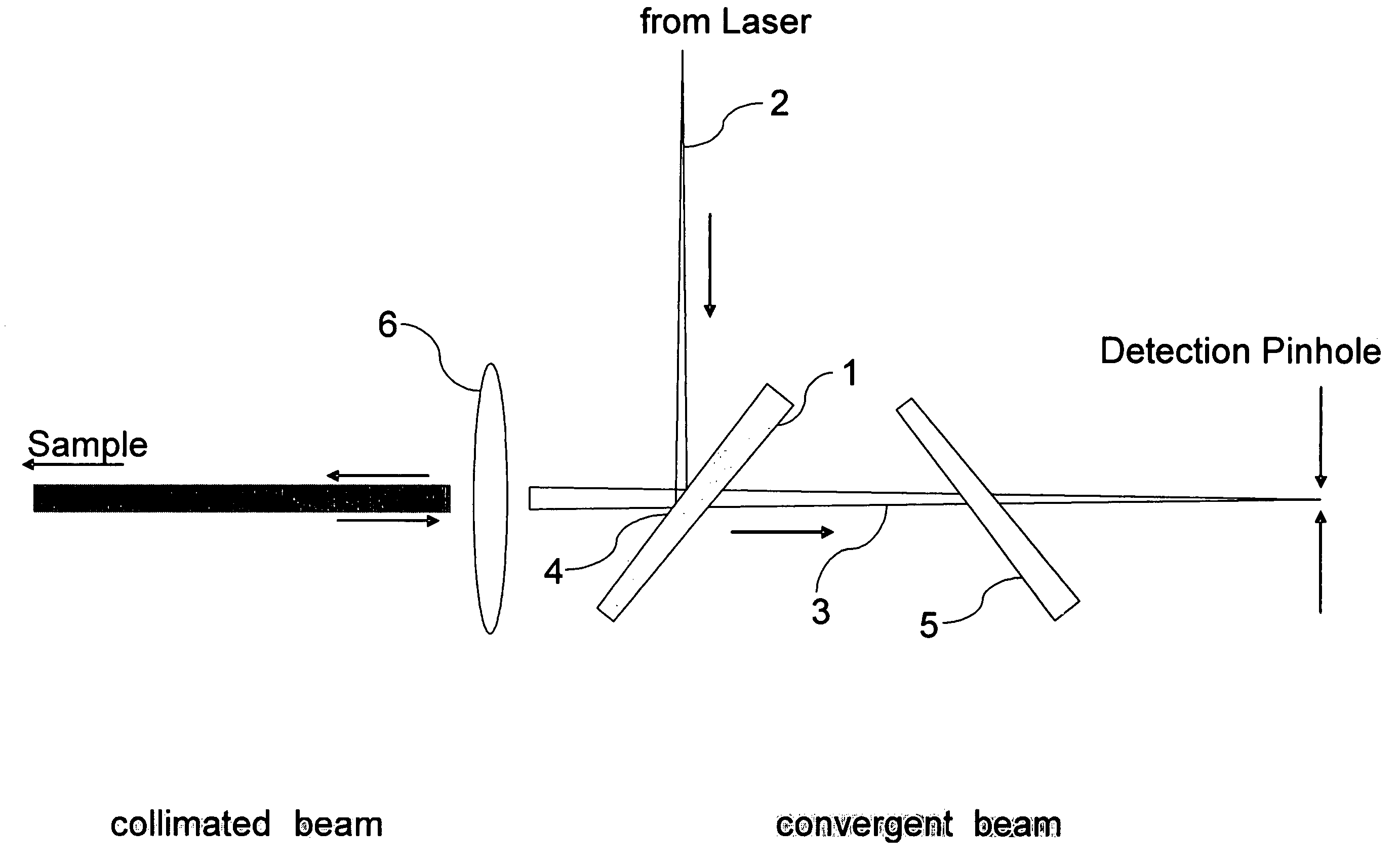
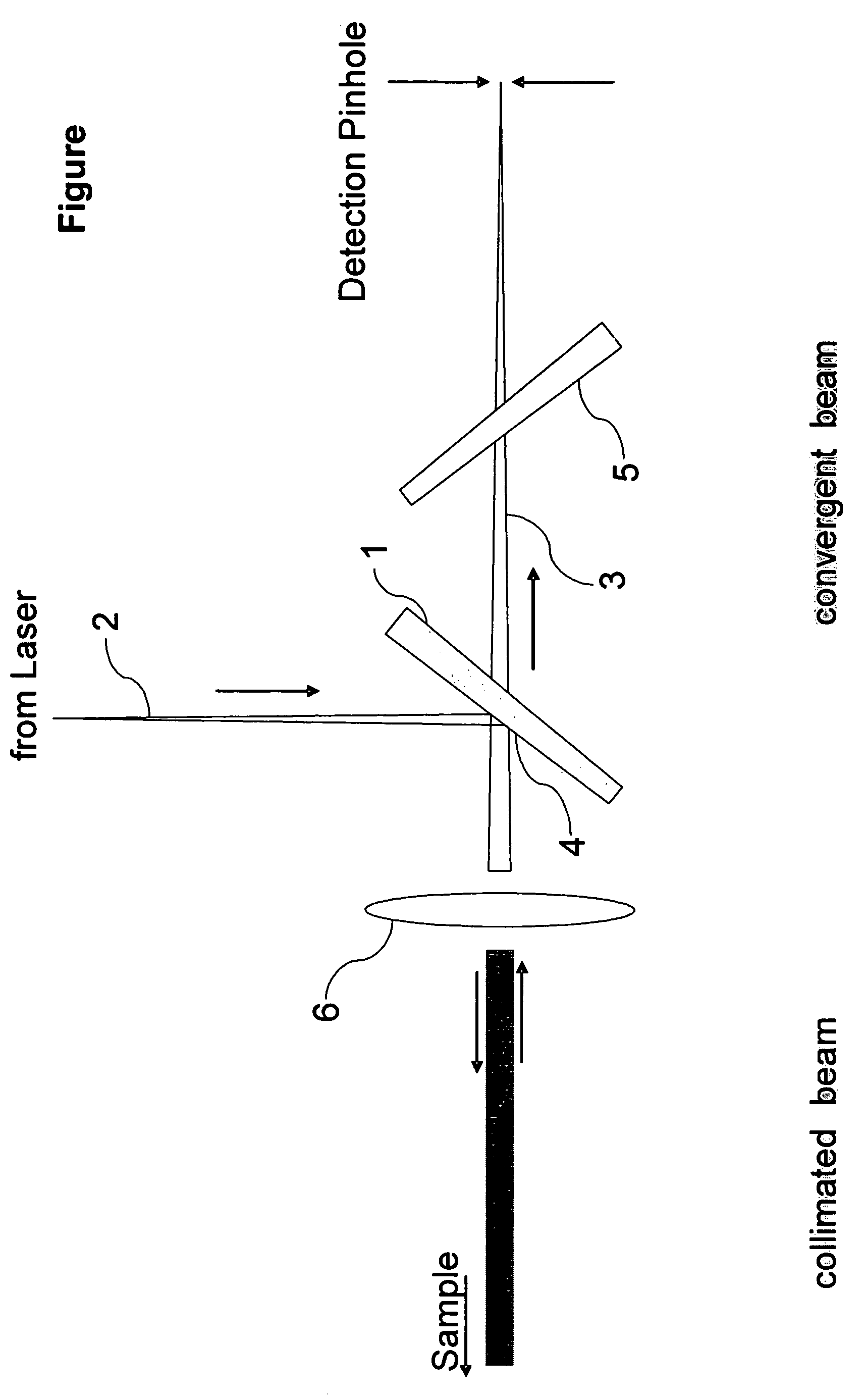
[0026]FIG. 1 shows a schematic representation of an embodiment of an optical arrangement for a microscope according to the invention. The optical arrangement exhibits a beam splitter 1 arranged in the divergent and convergent beam path for separating an illumination light 2 that is produced by an illumination source from a detection light 3 that is emitted by the sample being tested. With regard to reliable correction of imaging errors, even when using thick beam splitters, ...


PUM


Abstract

An optical arrangement for a microscope, in particular for a scanning microscope, with a beam splitter 1 arranged in a divergent and / or convergent beam path for separating an illumination light 2 that is produced by an illumination source from a detection light 3 that is emitted by a sample being tested, which with regard to reliable correction of imaging errors can be implemented and developed even when using thick beam splitters 1 such that the beam splitter 1 is wedge-shaped and implemented as a beam splitter plate for reflection primarily at a glass-air interface 4. Furthermore, a microscope with such an optical arrangement is disclosed.

Description

RELATED APPLICATIONS[0001]This application claims priority to German patent application number DE 10 2004 058 833.3, filed Dec. 6, 2004, which is incorporated herein by reference in its entirety.FIELD OF INVENTION[0002]The invention relates to an optical arrangement for a microscope, in particular for a scanning microscope, with a beam splitter arranged in a divergent and / or convergent beam path for separating an illumination light produced by an illumination source from a detection light emitted by a sample to he tested. The present invention further relates to a microscope, in particular to a scanning microscope, with such an optical arrangement.BACKGROUND OF THE INVENTION[0003]Optical arrangements of the aforementioned type are known from practice. For example, beam splitters are used in confocal laser scanning microscopes for separating the detection light that is present as fluorescent light, which carries the information about the sample, from the illumination light that is pr...

Claims


Application Information

Patent Timeline
Patent Type & Authority Patents(United States)
IPC IPC(8): G02B27/14G02B21/06
CPCG02B21/0032G02B27/144G02B27/16
Inventor RIEDMANN, JUERGEN
Owner LEICA MICROSYSTEMS CMS GMBH
Why Eureka
Try Eureka