Error identification method of machine tool and error identification system of the same

a technology of error identification and machine tools, which is applied in the direction of mechanical measuring arrangements, manufacturing tools, instruments, etc., can solve the problems of deteriorating process accuracy of workpieces, difficult to zero geometric errors, and deteriorating motion accuracy of machines, so as to reduce the load of operators of machines, not deteriorating the measurement accuracy of position measurement sensors, and reliably performing the calibration of position measurement sensors

Active Publication Date: 2017-10-19
OKUMA CORP
View PDF0 Cites 8 Cited by
  • Summary
  • Abstract
  • Description
  • Claims
  • Application Information

AI Technical Summary

Benefits of technology

[0036]With the disclosure, the calibration of the length and diameter compensation values of the position measurement sensor is possible during a sequence of respective measurements for the geometric error identification. The need for hand work except fix the preparation work in advance is eliminated. Accordingly, the preparation of an additional jig or a similar preparation is not required, ensuring a reduction in a load of an operator of the machine and reliably performing the c

Problems solved by technology

There is a geometric error between the respective axes such as an error in center position of the rotation axis (a displacement from an assumed position) and a tilt error of the rotation axes (squareness and parallelism between the axes) as a major factor of affecting motion accuracy of the five-axis-control machining center.
The geometric errors deteriorate the motion accuracy of the machine, deteriorating process accuracy of the workpiece.
In view of this, the geometric errors need to be reduced through adjustment but it is difficult to zero the geometric errors.
However, the methods in JP-A-4-63664 and JP-A-58-82649 have a problem of the necessity of additionally preparing another measuring device such as a dial gauge and a reference of, for example, a workpiece with a ring gauge and a bore.
Furthermore, since JP-A-4-63664, JP-A-5

Method used


Image

  • Error identification method of machine tool and error identification system of the same
  • Error identification method of machine tool and error identification system of the same
  • Error identification method of machine tool and error identification system of the same

Examples


Embodiment Construction

[0057]The following describes embodiments of the disclosure based on the drawings.

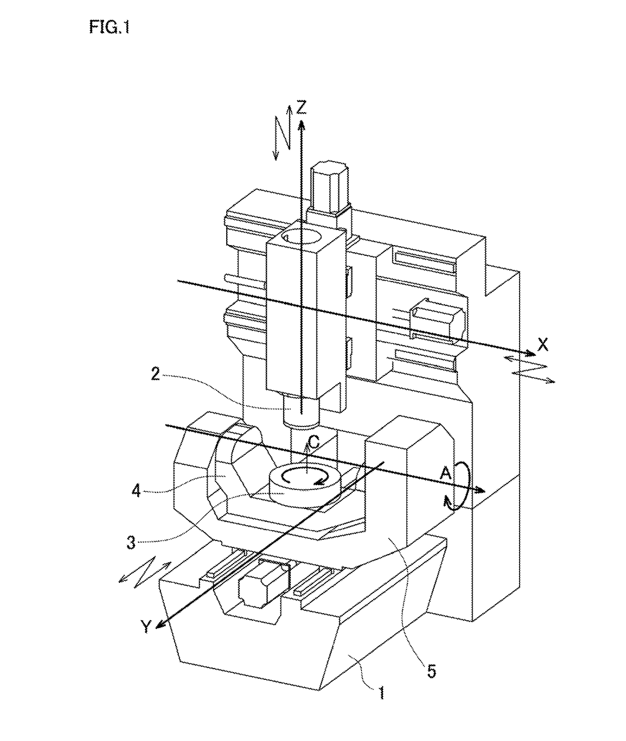
[0058]FIG. 1 is a schematic diagram of a machining center, which is one configuration of a machine tool, that includes three translational axes orthogonal to one another and two rotation axes orthogonal to one another. A motion of two degrees of freedom for translation of a main spindle 2 in an X-axis and a Z-axis, which are the translational axes and are orthogonal to one another, is possible with respect to a bed 1. A motion of one degree of freedom for rotation of a table 3 in a C-axis, which is the rotation axis, is possible with respect to a cradle 4. A motion of one degree of freedom for rotation of the cradle 4 in an A-axis, which is the rotation axis orthogonal to the C-axis, is possible with respect to a trunnion 5. A motion of one degree of freedom for translation of the trunnion 5 in a Y-axis, which is the translational axis and orthogonal to the X-axis and the Z-axis, is possible with respe...


PUM


Abstract

An error identification method includes a tool sensor position acquisition stage, a reference block position acquisition stage, a relative position calculation stage, a reference tool position acquisition stage, a position measurement sensor measurement stage, a length compensation value calculation stage, a diameter compensation value acquisition stage, a position measurement stage, a position compensation stage, and a geometric error identification stage. The diameter compensation value acquisition stage acquires a radial direction compensation value of the position measurement sensor with the measured jig. The position measurement stage indexes the rotation axis to a plurality of any given angles and measures respective positions of the measured jig. The position compensation stage compensates the position measurement value at the position measurement stage using the length direction compensation value and the radial direction compensation value. The geometric error identification stage identifies the geometric error from the plurality of position measurement values.

Description

BACKGROUND[0001]This application claims the benefit of Japanese Patent Application Numbers 2016-083860 filed on Apr. 19, 2016 and 2017-019723 filed on Feb. 6, 2017, the entirety of which is incorporated by reference.TECHNICAL FIELD[0002]The disclosure relates to a method that identifies a geometric error in a machine tool from a measurement result of a position of an object in the machine and a system that identifies the geometric error.RELATED ART[0003]FIG. 1 is a schematic diagram of a five-axis-control machining center that includes three translational axes and two rotation axes. A motion of two degrees of freedom for translation of a main spindle 2 in an X-axis and a Z-axis, which are the translational axes and are orthogonal to one another, is possible with respect to a bed 1. A motion of one degree of freedom for rotation of a table 3 in a C-axis, which is the rotation axis, is possible with respect to a cradle 4. A motion of one degree of freedom for rotation of the cradle 4 ...

Claims


Application Information

Patent Timeline
IPC IPC(8): B23Q17/22G01B5/008B23Q17/24
CPCB23Q17/2233G01B5/008B23Q17/2428B23Q17/22B23Q17/2414B23Q1/4857B23Q17/0923B23Q17/2461B23Q17/2485G01B21/045
Inventor MATSUSHITA, TETSUYAKANBE, REIJI
Owner OKUMA CORP
Why Eureka
Try Eureka