Brake control apparatus for vehicle

a technology for controlling apparatus and brakes, which is applied in the direction of braking systems, braking components, transportation and packaging, etc., can solve the problems of noise output from sensors used to control actuators, and the change of driving direction of the vehicle, so as to improve the stability of the driving state of the vehicle during braking, prevent the change of driving direction, and improve the safety of the driving state of the vehicl

Active Publication Date: 2009-07-28
HITACHI ASTEMO LTD
View PDF16 Cites 11 Cited by
  • Summary
  • Abstract
  • Description
  • Claims
  • Application Information

AI Technical Summary

Benefits of technology

[0009]In light of the above, an object of the present invention is to provide a brake control apparatus that does not cause a large difference in braking force between left and right vehicle wheels due to differences in graphs which each show the relationship between a motor position and a pad-pressing force and due to variations in each graph caused by aging and ambient temperature variations.
[0014]According to the present invention, the brake control apparatus estimates a pressing force by referring to a rigidity graph that is stored in advance and that shows the relationship between the motor position and the pad-pressing force. The rigidity graph can be compensated, corrected using the state of brake actuators obtained when the driving state of the vehicle is stabilized by operating brake devices during braking. Accordingly, it is possible to apply the same pressing force to the left and right wheels irrespective of the variation in the current sensor value used for constructing the rigidity graph and the variation in the rigidity of each actuator due to aging thereof. As a result, the stability of the driving state of the vehicle during braking can be increased and the safety in driving the vehicle can be improved.
[0015]When the process according to the present invention is performed at the timing of vehicle inspections, the rigidity graph can be reliably corrected at regular intervals. Accordingly, the safety in driving the vehicle can be prevented from being endangered due to aging of the brake devices.

Problems solved by technology

Therefore, signals output from sensors used to control the actuators include noise.
In such a case, the left and right wheels receive different braking forces and there is a risk that the driving direction of the vehicle will be changed due to braking, which is extremely dangerous.

Method used


Image

  • Brake control apparatus for vehicle
  • Brake control apparatus for vehicle
  • Brake control apparatus for vehicle

Examples


Embodiment Construction

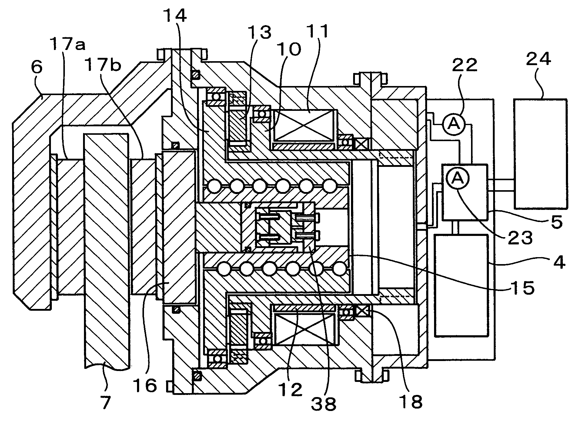
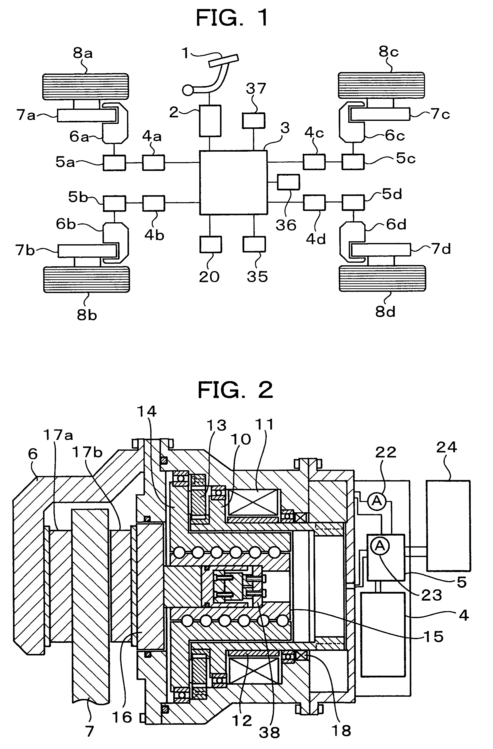
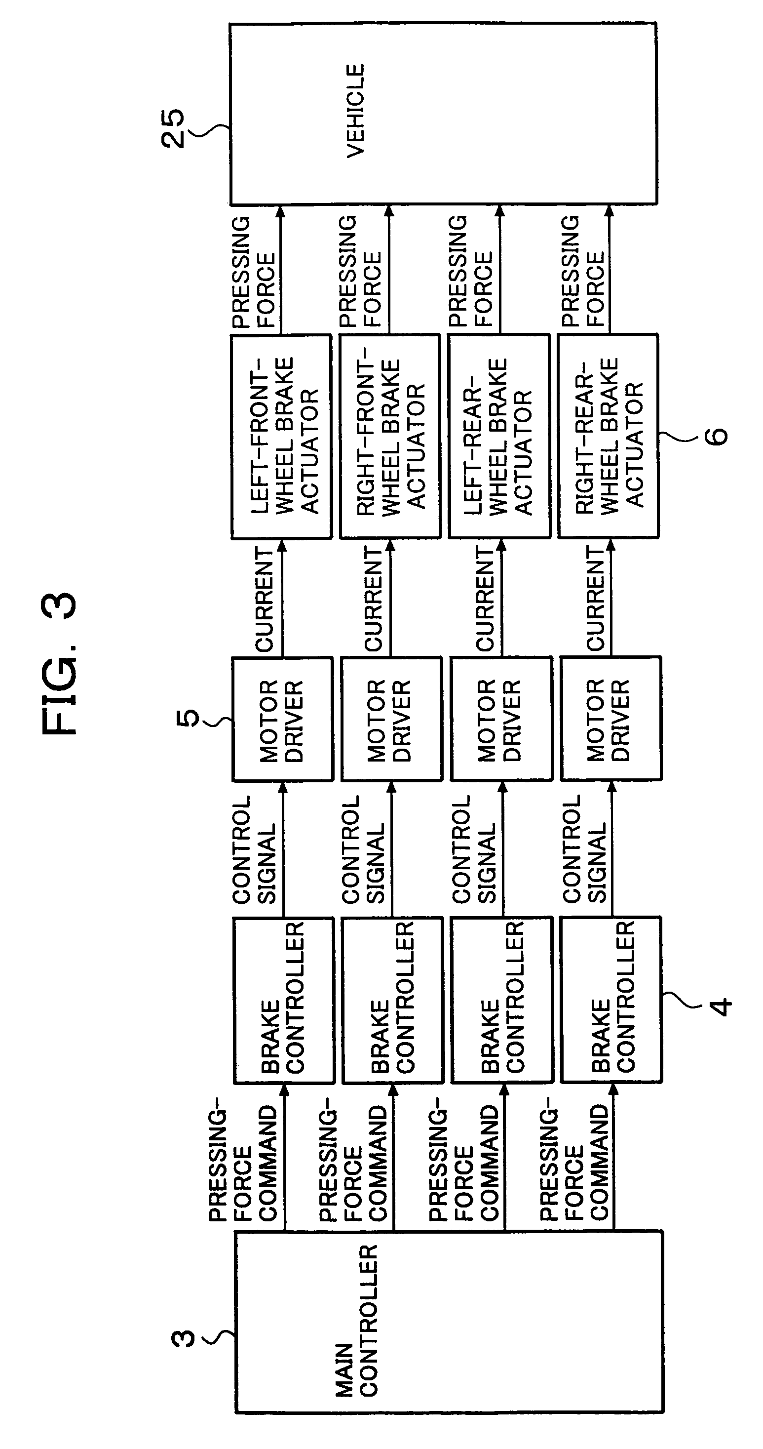
[0031]A brake control apparatus according to an embodiment of the present invention will be described in detail below with reference to FIGS. 1 to 14. FIG. 1 is a diagram illustrating the overall system structure of a vehicle including the brake control apparatus according to the embodiment of the present invention. More specifically, FIG. 1 shows a brake control system of the vehicle (for example, an automobile) having four wheels which each receive a braking force. Electric brake devices that function as brake devices for individually controlling the braking forces applied to the respective wheels are mounted on the vehicle.

[0032]Referring to FIG. 1, the vehicle includes wheels 8a to 8d; disc rotors 7a to 7d that rotate together with the respective wheels 8a to 8d; electric brake actuators 6a to 6d that slide along the respective disc rotors 7a to 7d while being pressed thereagainst; a brake pedal 1; a stroke sensor 2 that converts a displacement of the brake pedal 1 into an elect...


PUM


Abstract

A brake control apparatus for a vehicle having brake devices for generating pad-pressing forces at respective wheels includes brake control units for individually controlling the pad-pressing forces at the respective wheels; a storing unit for storing drive data required for controlling the pad-pressing force at each wheel; a vehicle-driving-state detector for detecting a driving state of the vehicle; and a vehicle controller for controlling a vehicle driving state using the brake control unit for each wheel. Memory data representing the relationship between a motor position and the pad-pressing force is updated using the state of brake actuators obtained when the driving state of the vehicle is stabilized by operating the brake devices during braking.

Description

BACKGROUND OF THE INVENTION[0001]1. Field of the Invention[0002]The present invention relates to a control apparatus for a brake device which can control a displacement of a piston using an electromotive device, such as a motor, and which generates a braking force by moving the piston so as to bring a brake friction member into contact with an object to be braked.[0003]2. Description of the Related Art[0004]Recently, various brake devices that can freely change a pressing force applied to a brake friction member using an electromotive device, such as a motor, have been suggested. A vehicle having such a brake device can perform brake control without being restricted by a brake command from a driver. Therefore, it is possible to improve both the safety in driving the vehicle and comfort. For example, Japanese Unexamined Patent Application Publication No. 2003-175816 discloses an electric brake system capable of synchronizing the times at which brake devices apply brakes to respective...

Claims


Application Information

Patent Timeline
Patent Type & Authority Patents(United States)
IPC IPC(8): F16D55/08
CPCB60T13/741
Inventor KAWAHARA, YOSHINARINOGAMI, TADAHIKONISHIGAITO, TAKAOMIYOKOYAMA, ATSUSHI
Owner HITACHI ASTEMO LTD
Why Eureka
Try Eureka