Graphics and monitor controller assemblies in multi-screen display systems

Inactive Publication Date: 2007-05-03
MOSCOVITCH GERALD
View PDF15 Cites 49 Cited by
  • Summary
  • Abstract
  • Description
  • Claims
  • Application Information

AI Technical Summary

Benefits of technology

[0011] The present invention thus makes use of the structure that would ordinarily just be used to support the LCD screen(s) to also house the central processing unit (CPU), one or more power supplies, and various cables typically used to couple the LCD screen(s) with the CPU and also to provide power

Problems solved by technology

With present day computer systems, the configuration of the system is often limited and does not provide for much flexibility in terms of being able to mix and match peripherals.
With systems employing a liquid crystal display (LCD) screen, there is often no means for easily attaching additional LCD screens, or for reconfiguring two or more existing screens, or for allowing easy and quick removal and/or replacement of one of more LCD screens of different sizes.
Another disadvantage with present day computer systems is the large number of electrical cables that must be used to couple the CPU with the peripherals.
As will be appreciated, these cables significantly clutter the user's work area.
When power

Method used


Image

  • Graphics and monitor controller assemblies in multi-screen display systems
  • Graphics and monitor controller assemblies in multi-screen display systems
  • Graphics and monitor controller assemblies in multi-screen display systems

Examples


first embodiment

[0047] Referencing now FIG. 5 the LCD support system 10 is shown with CPU 100 in an installed or docked position. CPU 100 includes vertically oriented connection ports 94 for suitably interfacing with an external pointing device, keyboard and the like. FIG. 6 illustrates an alternative configuration wherein a standalone base unit 112 is provided. The standalone base unit 112 may be used when viewing multiple screens is not required. While not specifically shown, a dual connection port arrangement may also be employed in a side-by-side relationship such that two CPU units 100 may be concurrently docked. Such a setup would provide further memory or processing capability when additional computing resources are desired. In each scenario, the pins and receivers incorporated on the CPU interface portion 14 are configured to mate with complimentary pins and receivers (not specifically shown) disposed on a bottom face of the CPU. As shown in FIG. 7, CPU 100 includes a hingedly attached doo...

second embodiment

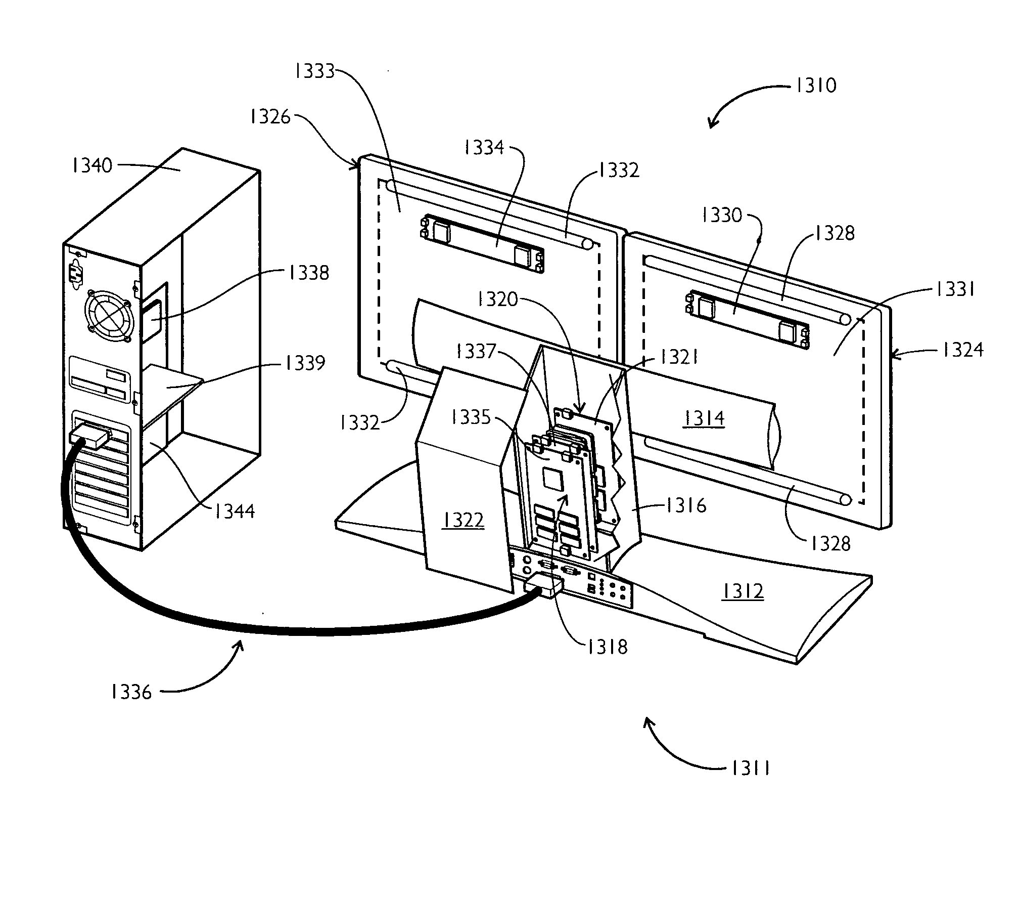
[0048] Turning now to FIGS. 8-10, the present invention will be described wherein like reference numbers increased by 100 will be used to designate components corresponding to system 10. In this regard, LCD support system 120 includes base 112 shown in cooperative engagement with vertical arm 160. A pair of grooves (not specifically shown) are arranged along opposing inner walls 162 of column 120 to interface with a pair of tongues 164 extending along opposite sides of the arm 160. First and second slider brackets 128 are coupled for slidable engagement with vertical arm 160. First and second pivot brackets 138 selectively couple to first and second slider brackets 128 to provide pivotal movement for a mounted LCD viewing screen. Such a configuration provides for first and second LCD screens to be adjacently mounted in a vertical orientation.

third embodiment

[0049] Turning now to FIG. 11, the present invention will be described wherein like reference numbers increased by 200 over those used in connection with system 10 will be used to designate like components. As shown, LCD support system 200 includes a vertical arm 260 mounted to the central portion 222 of upright column 220 as previously described. In addition, a slider bracket (not specifically shown) operably interconnects dual LCD support arm 232 to a lower portion of vertical arm 260. This arrangement provides a pyramid configuration in which three LCD screens may be selectively mounted to pivot brackets 238 in a triangular relationship.


PUM


Abstract

A multi-monitor display system is described having an arm adapted for supporting a plurality of monitors containing display screens. The system also includes a column for supporting the arm, a monitor controller assembly for electronically controlling images displayed on the screens, and a graphics assembly for sending signals to the monitor controller assembly to produce the images. The system is used in conjunction with a central processor located in a computer housing. The monitor controller assembly is disposed outside of the monitors and/or the graphics assembly is disposed outside the computer housing.

Description

CROSS REFERENCE TO RELATED APPLICATIONS [0001] This application is a continuation-in-part of U.S. application Ser. No. 10 / 170,826 filed Jun. 13, 2002, and also claims priority to U.S. provisional application No. 60 / 597,045 filed on Nov. 7, 2005.FIELD OF THE INVENTION [0002] The present invention generally pertains to computer systems, and more particularly to graphics and monitor controller assemblies in multi-screen display systems. BACKGROUND OF THE INVENTION [0003] With present day computer systems, the configuration of the system is often limited and does not provide for much flexibility in terms of being able to mix and match peripherals. This is especially so for the display portion of the system. With systems employing a liquid crystal display (LCD) screen, there is often no means for easily attaching additional LCD screens, or for reconfiguring two or more existing screens, or for allowing easy and quick removal and / or replacement of one of more LCD screens of different size...

Claims


Application Information

Patent Timeline
IPC IPC(8): G06F1/16
CPCF16M11/04F16M11/14F16M11/2085F16M11/24F16M2200/065G06F1/1601G06F3/1431G06F3/1438G09G2370/04F16M2200/022G06F3/1423
Inventor MOSCOVITCH, GERALD
Owner MOSCOVITCH GERALD
Why Eureka
Try Eureka