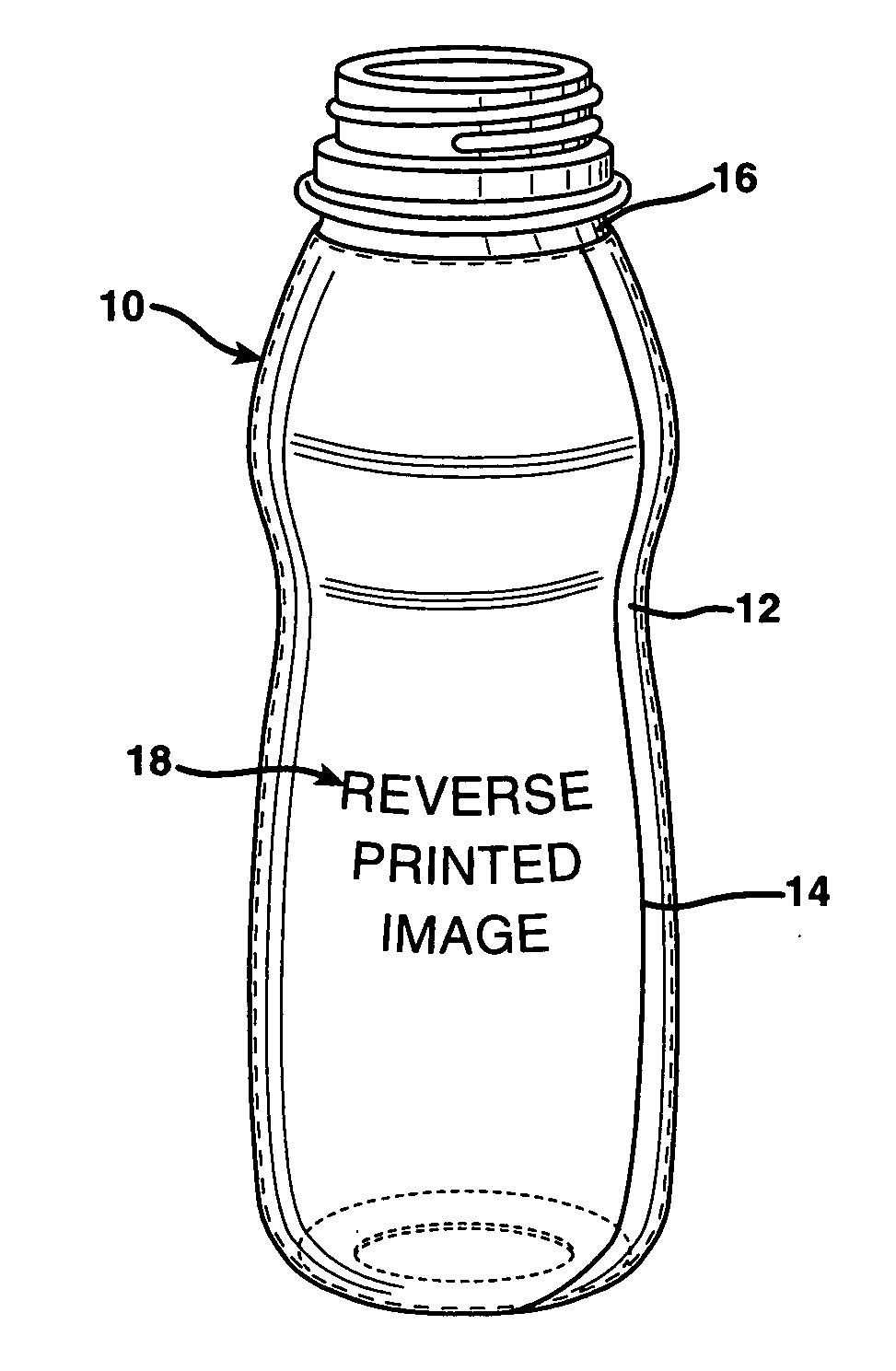
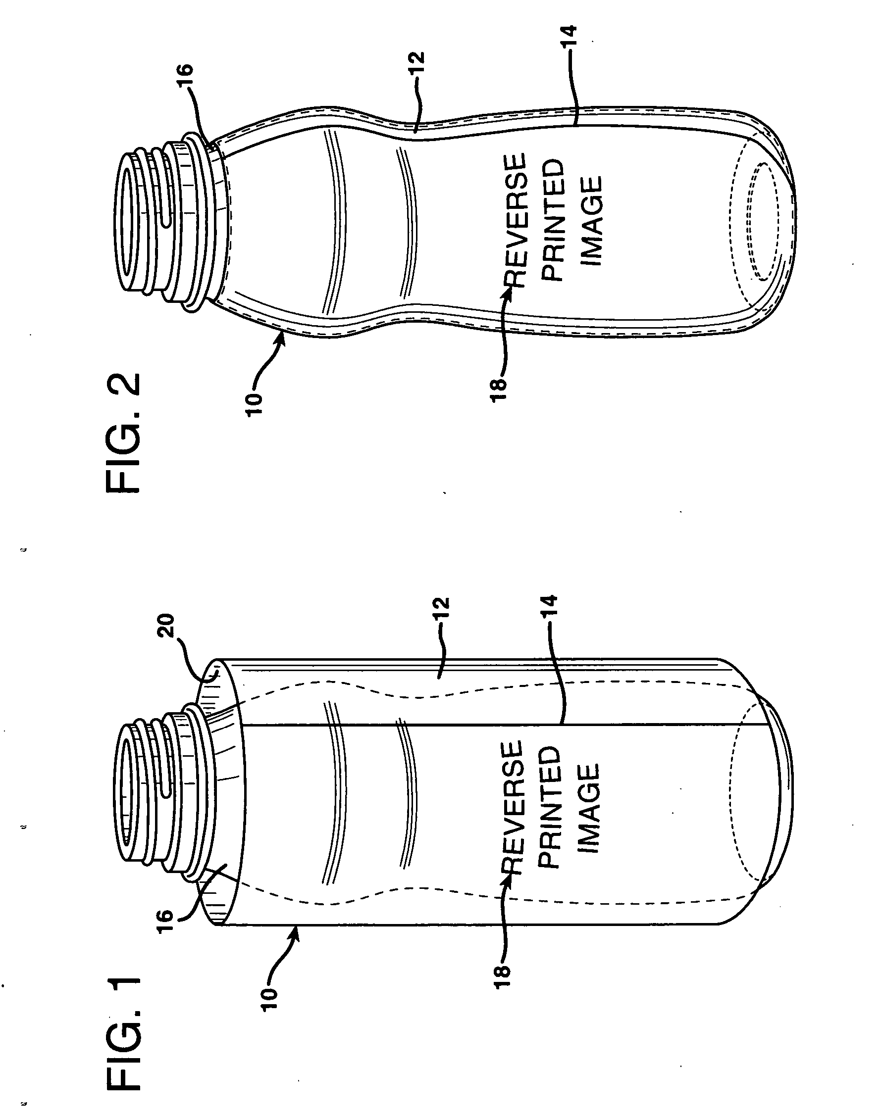
Shrink sleeve label
a technology of shrink sleeve and label, which is applied in the direction of stamps, rigid containers, synthetic resin layered products, etc., can solve the problem of film having an undesired low young's modulus for shrink sleeve end us
- Summary
- Abstract
- Description
- Claims
- Application Information
AI Technical Summary
Benefits of technology
Problems solved by technology
Method used
Image
Examples
example 1
[0110] A three-layer film was made by extruding a film having an A / B / A film layer configuration where the “A” skin layers were PETG1 and the “B” base layer was a blend of 50 wt. % LLDPE1, 25 wt. % COC1, and 25 wt. % COC2. After orientation, the film was quenched to lock in the orientation. The thickness ratio of the layers was 1:8:1. The shrink initiation temperature for the film was about 40° C. The Young's modulus of the shrink film was about 285,000 psi. Table 1 below shows the percent free shrink in the transverse direction (TD) and machine direction (MD) at various temperatures.
example 2
[0111] A film was made by extruding a film having an A / C / B / C / A film configuration. The “A” skin layers were 99 wt. % PETG1 and 1 wt. % AB1. The “B” base layer was 80 wt. % VLDPE1 and 20 wt. % COC2. The “C” intermediate layers were 50 wt. % VLDPE1 and 50 wt. % Tie1. The extruded film was oriented in the transverse direction in a ratio of about 6:1 at a temperature of about 205° C. After orientation, the film was quenched to lock in the orientation. The resulting film had a thickness of 1.75 mils. The layer thicknesses as a percentage of the total film thickness were 8% / 8% / 68% / 8% / 8%. The density of the film was 0.96 g / cc. The Young's modulus of the film was about 155,000 psi. Table 1 below shows the percent free shrink in the transverse direction (TD) at various temperatures.
example 3
[0112] A three-layer film was made by extruding a film having an A / B / A film layer configuration where the “A” skin layers were PETG1 and the “B” base layer was a blend of 80 wt. % VLDPE1 and 20 wt. % COC1. After orientation, the film was quenched to lock in the orientation. The thickness ratio of the layers was 1:8:1. Table 1 below shows the percent free shrink in the transverse direction (TD) and machine direction (MD) at various temperatures.
TABLE 1Example 1Example 1Example 2Example 3Example 3Temper-% Free% Free% Free% Free% FreeatureShrinkShrinkShrinkShrinkShrink(° C.)(TD)(MD)(TD)(TD)(MD)350040114544005099005526260160504605166560562840706662586271.1475677082.23093.363104.479115.681
[0113] Any numerical value ranges recited herein include all values from the lower value to the upper value in increments of one unit provided that there is a separation of at least 2 units between any lower value and any higher value. As an example, if it is stated that the amount of a component or a...
PUM
| Property | Measurement | Unit |
|---|---|---|
| Temperature | aaaaa | aaaaa |
| Temperature | aaaaa | aaaaa |
| Fraction | aaaaa | aaaaa |
Abstract
Description
Claims
Application Information
 - R&D
- Intellectual Property
- Life Sciences
- Materials
- Tech Scout
- Unparalleled Data Quality
- Higher Quality Content
- 60% Fewer Hallucinations
Browse by: Latest US Patents, China's latest patents, Technical Efficacy Thesaurus, Application Domain, Technology Topic, Popular Technical Reports.
© 2025 PatSnap. All rights reserved.Legal|Privacy policy|Modern Slavery Act Transparency Statement|Sitemap|About US| Contact US: help@patsnap.com


