Fishing lure

Inactive Publication Date: 2007-05-10
RIKE EDKOR DAVID
View PDF13 Cites 7 Cited by
  • Summary
  • Abstract
  • Description
  • Claims
  • Application Information

AI Technical Summary

Benefits of technology

[0007] It is a further object to provide a fishing lure with increased action when pulled through water.
[0010] Accordingly, the present invention is directed to a novel fishing lure. The lure includes a hollow body having tongue extending forwardly from the body to which a fishing line can be attached. The body also includes a hook attached thereto. Proximate the point of connection of the tongue to a front of the body there is an inlet channel defined in the body. The inlet channel communicably connects to a bladed wheel chamber which houses a multi-bladed wheel which is disposed within the bladed wheel chamber to rotate about an axis generally transverse to a flow path from the inlet channel through the blade chamber. There is an outlet channel defined in a bottom of the body which communicates with the bladed wheel chamber. The inlet channel can be configured within the body to communicate with a portion of the bladed wheel chamber such that the flow path is introduced to the bladed wheel chamber on one side of the axis to force against a blade extending from the multi-bladed wheel and cause rotation thereof as the flow path continues through the outlet channel. The body can be translucent and the multi-bladed wheel surface can be colored, reflective, or luminescent, to create a desired attractive appearance within the body. The outlet channel can be relatively smaller than the inlet channel and chamber such that a Venturi effect can be created. The tongue can be pitched downwardly relative to a horizontal axis of the body. The body can be configured with any desired head end and tail end to resemble desired bait.

Problems solved by technology

Still other lures produce noise via the spinners as they rotate.

Method used


Image

  • Fishing lure
  • Fishing lure

Examples


Embodiment Construction

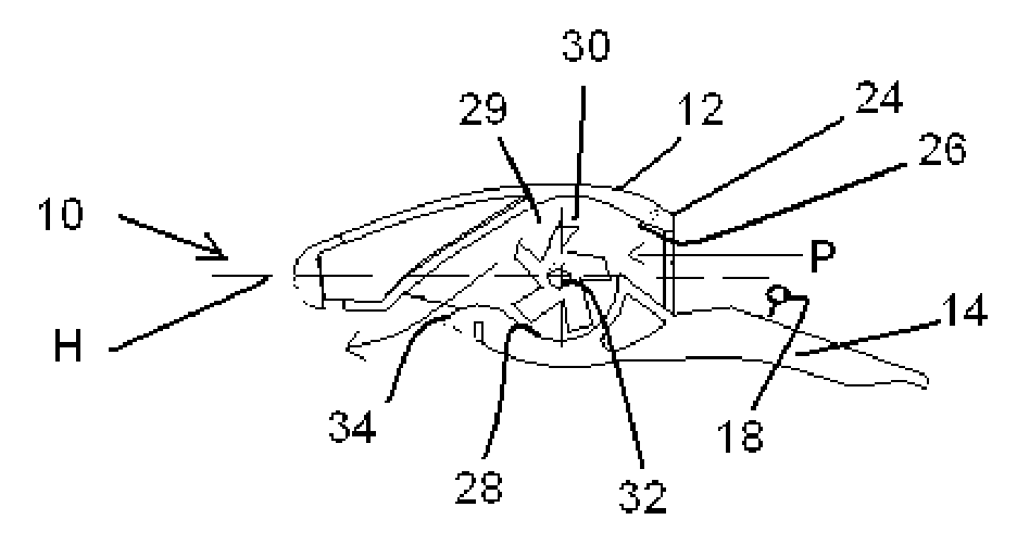
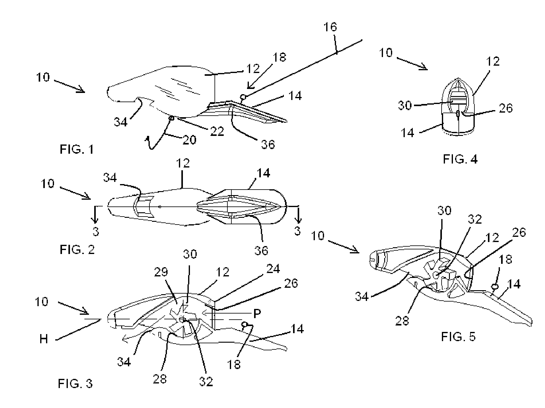
[0017] Referring now to the drawings, the lure of the present invention is generally designated by the numeral 10. The lure 10 includes a hollow body 12 having tongue 14 extending forwardly from the body 12 to which a fishing line 16 can be attached to a connector 18 on the tongue 14. The tongue 14 can be angled or pitched to downwardly extend relative to a horizontal axis H of the body 12.

[0018] The body 12 includes a hook 20 which can be attached to a bottom 22 of the body 12. Proximate the point of connection of the tongue 14 to a front portion 24 of the body 12 there is an inlet channel 26 defined in the body 12 to receive water therethrough. The inlet channel 26 communicably connects to a bladed wheel chamber 28 which houses a multi-bladed wheel 30. The bladed wheel 30 is disposed within the blade chamber 28 to rotate about a hub bearing surface 32 extending inwardly from the body 12 on an axis generally transverse to a flow path P from the inlet channel 26 through the bladed ...


PUM


Abstract

A lure includes a hollow body having tongue extending forwardly from the body to which a fishing line can be attached and the body includes a hook attached thereto, an inlet channel is defined in the body and communicably connects a bladed wheel chamber which houses a multi-bladed wheel which rotates about an axis generally transverse to a flow path from the inlet channel through the blade chamber and out an outlet channel which communicates with the blade chamber.

Description

FIELD OF THE INVENTION [0001] This invention relates to fishing lures and more particularly to a fishing lure which is retained and pulled by attachment to a fishing line controlled by the user. [0002] Such lures have been used for many years in place of live bait for either cost purposes or with the belief that such lure offers advantages in attracting fish more readily than live bait, i.e., the belief that certain artificial baits may be as or more appealing to certain fish or certain fish-situations than live bait. These beliefs precipitate an annual surge in production of various lure types and are common instruments in modern fishing accessories. [0003] Common features of a lure include a hook(s) and a body which serves as the attracting feature enabling hooking of the fish. The hook and body design vary widely in design shape, number and weight which in turn affects the lure's ability to be readily cast as well propelled through the water. The lure's structural and aesthetic f...

Claims


Application Information

Patent Timeline
IPC IPC(8): A01K85/00
CPCA01K85/01
Inventor RIKE, EDKOR DAVID
Owner RIKE EDKOR DAVID
Why Eureka
Try Eureka