
Intraosseous dental implant

Active Publication Date: 2020-07-09
PLAN 1 HEALTH
View PDF0 Cites 0 Cited by
  • Summary
  • Abstract
  • Description
  • Claims
  • Application Information

AI Technical Summary

Benefits of technology

The patent text describes a design for an implant that increases its grip on the bone by tapering towards the apical and coronal portions and distributing torsion tenses evenly along its length. This improves stability and durability over time, even when subjected to stresses such as chewing, and allows for easier screwing during installation.

Problems solved by technology

This determines a reduction in the gripping capacity of the implant since, when the latter is inserted into the bone part, the first portion which is inserted first erodes part of the bone and jeopardizes the subsequent anchorage of the second portion.
This manufacturing procedure, as well as the particular conformation of the implant, entail that an unstable anchorage is obtained in the bone part, since the conical portions do not have a uniform grip along their whole axial extension because of the differences in coupling between the hole which has a cylindrical conformation and the different portions of the implant that have a conical conformation.
This conformation of the implant is also particularly unstable during installation as it cannot provide sufficient grip during use.
Therefore, one of the disadvantages of known dental implants is the precarious anchorage to the bone part of the patient, which the shaft described above does not always guarantee in a safe and lasting manner over time.
The precarious anchorage is even more pronounced when the conditions of the patient's bone part are not optimal.
In fact, it is not rare that, due to a badly or improperly anchored dental implant, a dental prosthesis must be removed and replaced, with consequent physical and economic damage for the patient.
Furthermore, once a dental implant has been installed, normally the waiting time to achieve a sufficiently stable anchorage, that is, the osseointegration time of the implant, is excessively long.

Method used


Image

  • Intraosseous dental implant
  • Intraosseous dental implant

Examples


Embodiment Construction

[0044]We will now refer in detail to the various embodiments of the present invention, of which one or more examples are shown in the attached drawings. Each example is supplied by way of illustration of the invention and shall not be understood as a limitation thereof. For example, the characteristics shown or described insomuch as they are part of one embodiment can be adopted on, or in association with, other embodiments to produce another embodiment. It is understood that the present invention shall include all such modifications and variants.

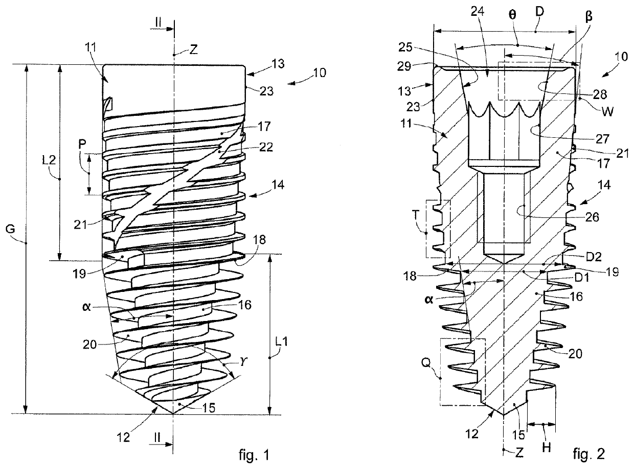
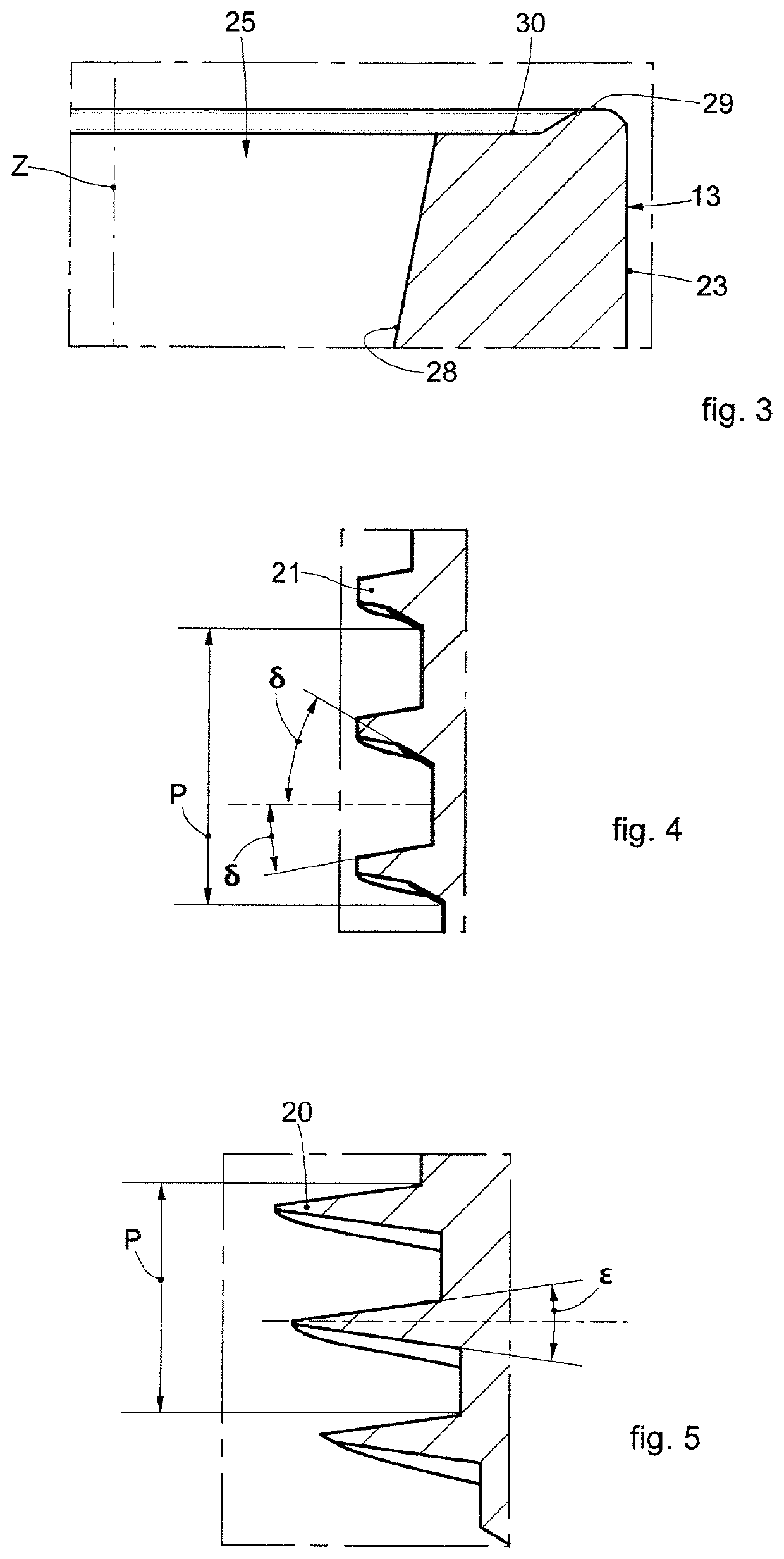
[0045]Embodiments described here using FIGS. 1-5 concern a dental implant 10, for dental use, comprising a shaft 11.

[0046]The shaft 11 can be made of biocompatible metal material, for example titanium.

[0047]The shaft 11 has an oblong development along a longitudinal axis Z.

[0048]The shaft 11 has an axial-symmetric shape to allow it to be screwed in.

[0049]The shaft 11 can have a length G which, by way of example only, can be comprised betwee...


PUM


Abstract

Intraosseous dental implant comprising a shaft (1 1) provided with a first end (12), a second end (13) opposite the first end (12), and at least one threading (14) made on the external surface of the shaft (1 1).

Description

FIELD OF THE INVENTION[0001]The present invention concerns a dental implant, for dental use, of an osteointegrable type and usable in the field of dental prostheses.BACKGROUND OF THE INVENTION[0002]Intraosseous dental implants are known, having substantially the shape of a screw to be fixed or anchored, by screwing, into a hole made in the bone part, that is, in the maxillary or mandibular bone, of a patient.[0003]The dental implant, once in use, is associated with its accessories, for example with stumps, with prosthetic components or dedicated instruments, intended to restore the masticatory, aesthetic and phonetic function and the gnathological coordination of the patients, thus eliminating the need for traditional mobile prostheses.[0004]Dental implants are usually made of a biocompatible metal material, for example titanium.[0005]Normally, an intraosseous dental implant is defined by a shaft with a truncated cone shape with a single taper that develops along the longitudinal ex...

Claims


Application Information

Patent Timeline
IPC IPC(8): A61C8/00
CPCA61C8/0045A61C2008/0046A61C8/006A61C8/0022
Inventor ROCCI, ANTONIOBAGGI, LUIGICAVENAGO, MAURO
Owner PLAN 1 HEALTH
Learn More