
Pneumatic tire

a pneumatic tire and tire body technology, applied in the field of pneumatic tires, can solve the problems of biased wear such as toe-and-heel wear or the like, and the normal studless tire cannot generate sufficient driving force and braking force, and achieve the effect of effectively dischargeing snow, improving driving performance, and improving the edge effect of the block

Active Publication Date: 2007-05-10
TOYO TIRE & RUBBER CO LTD
View PDF10 Cites 18 Cited by
  • Summary
  • Abstract
  • Description
  • Claims
  • Application Information

AI Technical Summary

Benefits of technology

[0010] Accordingly, an object of the present invention is to provide a pneumatic tire which can increase a driving performance on a road surface of a so-called sherbet snow, and in which a biased wear such as a toe-and-heel wear or the like is hard to be generated.
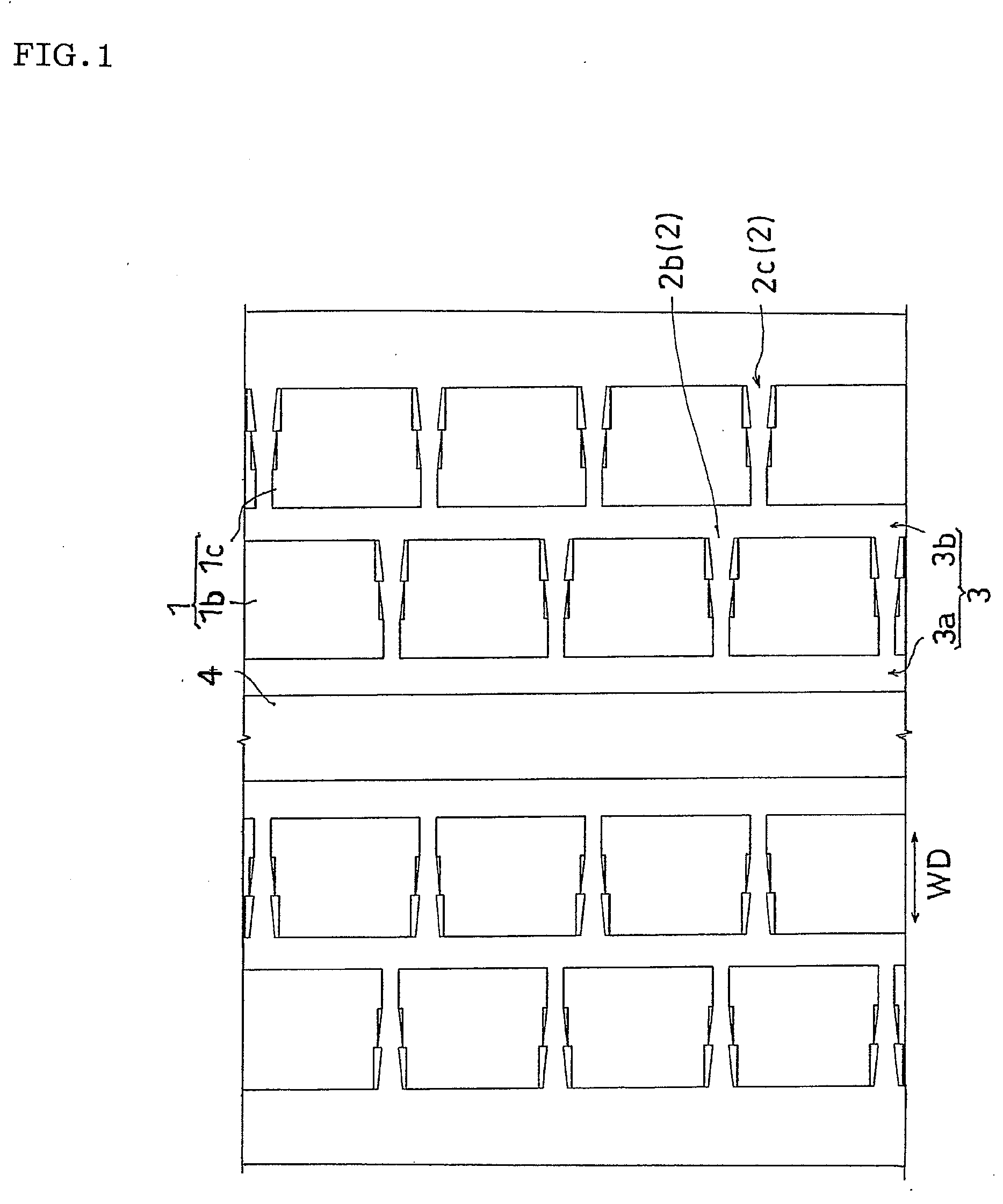
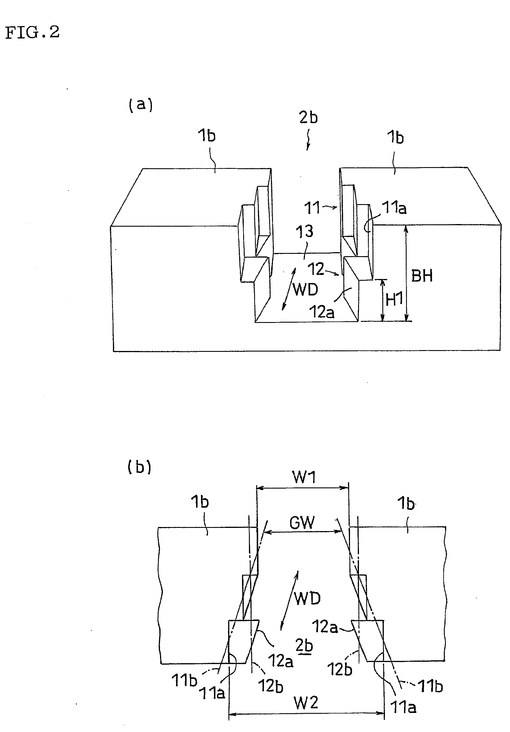
[0015] In accordance with the pneumatic tire on the basis of the present invention, since the transverse groove has the top side groove portion extending while the groove width expands to the tread end side, it is possible to effectively discharge the snow in the sherbet state to the tread end side, so that it is possible to increase the driving performance on the road surface of the sherbet snow. At this time, since the transverse groove has the bottom side groove portion extending with a roughly fixed groove width, a rigidity in a lower side of the block can be maintained, so that a biased wear such as a toe-and-heel wear or the like is hard to be generated.
[0016] In the structure mentioned above, it is preferable that at least the top side groove portion has a zigzag wall surface. Since at least the top side groove portion has the zigzag wall surface, whereby an edge length and an edge direction of the block are increased, it is possible to further improve an edge effect of the block.
[0017] Further, it is preferable that the bottom side groove portion of the transverse groove is provided from the bottom surface to a height of 15 to 50% of the block height, and the remaining portions are formed as the top side groove portion. The rigidity in the lower side of the block can be sufficiently maintained by forming the bottom side groove portion of the transverse groove in the region mentioned above, and it is possible to more effectively discharge the snow in the sherbet state by the tread end side on the basis of the remaining top side groove portion.
[0018] Further, it is preferable that the transverse groove is provided within a region of 0 to 50% of the tread width from the tread ends in both sides. This region corresponds to a region in which the biased wear such as the toe-and-heel wear or the like tends to be generated, particularly by the driving on a dry and wet road surface, and it is possible to effectively increase a driving performance on the snowed road surface, by discharging the snow in the sherbet state to the tread end side in this region.

Problems solved by technology

In general, various types of tread patterns are formed in the pneumatic tire for preventing a slip with respect to a road surface during the driving, however, since a performance of the tire having the normal tread pattern is inferior on an iced or snowed road, a special tire is used for driving on the frozen road.
However, in the case that an air temperature rises and the iced and snowed road is in a so-called sherbet state, there is a lot of cases that the normal studless tire can not generate the sufficient driving force and braking force.
However, in the studless tire, since groove widths of the drain groove coupling the respective portions and the drain grooves connected to the tread end are narrow, it can not be said that a draining effect is sufficient with respect to the road surface on the snow in the sherbet state, a state close to a hydroplaning tends to be generated, and a sufficient driving performance is hard to be obtained.
However, in this case, since the rigidity of the block is partly lowered in the portion having the wide groove width due to the different width of the transverse groove, a biased wear such as a toe-and-heel wear or the like tends to be generated.

Method used


Image

  • Pneumatic tire
  • Pneumatic tire
  • Pneumatic tire

Examples


example 1

[0051] In the tread pattern shown in FIG. 4, the height of the block is fixed to 9 mm, the widths of the transverse groove 2a and 2c are fixed to 7 mm, the width of the top side groove portion 11 of the transverse groove 2b is changed from 6 mm of the minimum to 8 mm of the maximum, as shown in FIGS. 1 and 2, the width of the bottom side groove portion 12 (50% height) of the transverse groove 2b is fixed to 6 mm, the width of the peripheral groove 3a is set to 7 mm, and the width of the peripheral groove 3b is set to 7 mm, whereby a radial tire of size 205 / 65R15 is manufactured. Table 1 shows the result obtained by executing the respective performance evaluations mentioned above by using the tire.

example 2

[0052] In Example 1, the same structures as Example 1 are employed except that the structure that the top side groove portion 11 and the bottom side groove portion 12 are formed in the same manner as the case of the transverse groove 2 with respect to the transverse groove 2c, whereby the radial tire is manufactured. Table 1 shows the result obtained by executing the respective performance evaluations mentioned above by using the tire.


PUM


Abstract

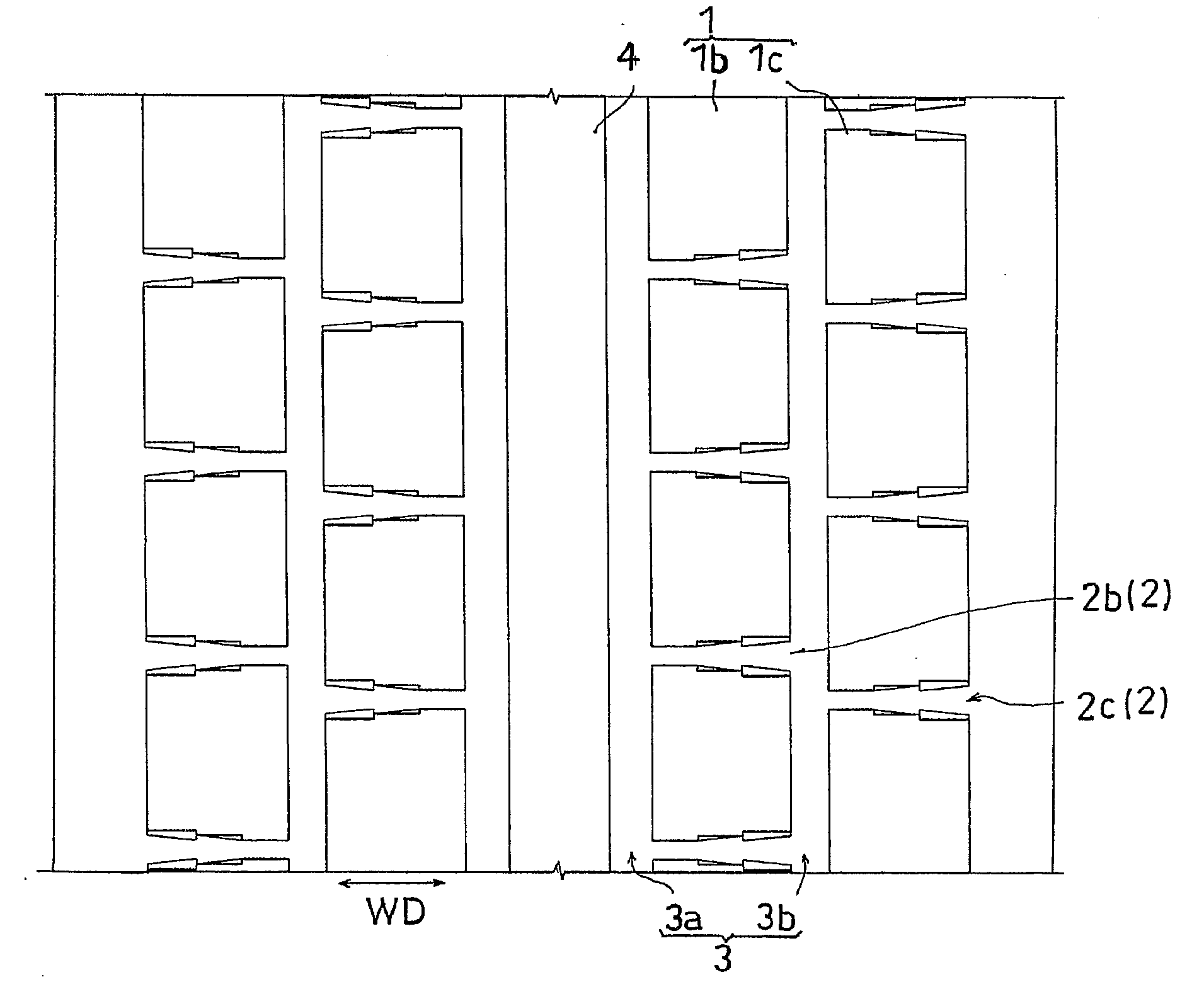
The invention provides a pneumatic tire which can increase a driving performance on a road surface of a so-called sherbet snow, and in which a biased wear such as a toe-and-heel wear or the like is hard to be generated. In a pneumatic tire provided with a tread pattern having a transverse groove 2b formed between a plurality of blocks 1b, the transverse groove 2b is provided with a top side groove portion 11 extending while a groove width GW expands to a tread end side, and a bottom side groove portion 12 extending with a roughly fixed groove width GW.

Description

BACKGROUND OF THE INVENTION [0001] 1. Field of the Invention [0002] The present invention relates to a pneumatic tire provided with a tread pattern having a transverse groove formed between a plurality of blocks, and is particularly useful for a studless tire. [0003] 2. Description of the Related Art [0004] In general, various types of tread patterns are formed in the pneumatic tire for preventing a slip with respect to a road surface during the driving, however, since a performance of the tire having the normal tread pattern is inferior on an iced or snowed road, a special tire is used for driving on the frozen road. [0005] As the tire mentioned above, a studless tire using no metal stud becomes popular at present. The studless tire has a comparatively soft rubber tread, is provided with a lot of blocks on a surface thereof in a projecting manner, and is generally structured such that a plurality of sipes (narrow grooves) is formed in a tire width direction with respect to each of ...

Claims


Application Information

Patent Timeline
IPC IPC(8): B60C11/13
CPCB60C11/0309B60C11/0316B60C11/13Y10S152/902
Inventor OHASHI, TOSHIYUKI
Owner TOYO TIRE & RUBBER CO LTD
Learn More