Occupant protection apparatus

a technology for occupants and protective devices, applied in the direction of pedestrian/occupant safety arrangements, vehicular safety arrangements, transportation and packaging, etc., can solve the problems of increasing the difficulty of space security, and achieve the effect of reducing the area of the cover sheet which covers the window and suppressing the area of the cover sh

Inactive Publication Date: 2007-05-10
TOYODA GOSEI CO LTD
View PDF13 Cites 15 Cited by
  • Summary
  • Abstract
  • Description
  • Claims
  • Application Information

AI Technical Summary

Benefits of technology

[0027] In the configuration like this, when the cover sheet has completely deployed, since the end portion of the upper side part thereof which lies far apart from the support member is positioned lower in height than the end portion which lies toward the support member, the cover sheet is made difficult to rise. Namely, the end portion of the upper side part of the cover sheet which lies far apart from the support member is made difficult to approach the support member, and in conjunction with the configuration where the end portion of the upper side part of the cover sheet which lies toward the support member is controlled with respect to its position by the stopper mechanism so as not to move apart from the support member, the front and rear edges of the cover sheet themselves are prevented from moving toward the center of the window, whereby the reduction in area of the cover sheet which covers the window can be suppressed further when and after the cover sheet has completely deployed to hold the occupant.
[0028] In addition, when a stopper mechanism is provided between the cover sheet and the pulling string, apart from the aforesaid first stopper mechanism which is provided between the passageway portion on the upper side part of the cover sheet which lies toward the support member, a secondary stopper mechanism may be provided further on the portion of the upper side part of the cover sheet where the passageway portion lying toward the fixed end of the pulling string is provided and the pulling string such that constituent parts of the secondary mechanism are brought into engagement with each other so as to prevent the portion of the upper side part of the cover sheet where the relevant passageway portion is provided from moving toward the support member when the cover sheet is completely deployed.
[0029] In the configuration like this, the end portion of the upper side part of the cover sheet which lies far apart from the support member is made difficult to approach the support member by the secondary stopper mechanism, and in conjunction with the configuration where the end portion of the upper side part of the cover sheet which lies toward the support member is controlled with respect to its position by the first stopper mechanism so as not to move apart from the support member, both the front and rear edges of the cover sheet themselves are prevented from moving toward the center of the window, whereby the reduction in area of the cover sheet which covers the window can be suppressed further when and after the cover sheet has completely deployed to hold the occupant.

Problems solved by technology

However, the front and rear edges of the window peripheral edge constitute areas where a space for accommodation or installation of the cover sheet is difficult to be secured, and in particular, in a door such as a front side door or rear side door, the securing of the space gets more difficult, and hence, it has been desired that the cover sheet is accommodated on the lower edge portion of the window peripheral edge where the accommodation space is easy to be secured.

Method used


Image

  • Occupant protection apparatus
  • Occupant protection apparatus
  • Occupant protection apparatus

Examples


first embodiment

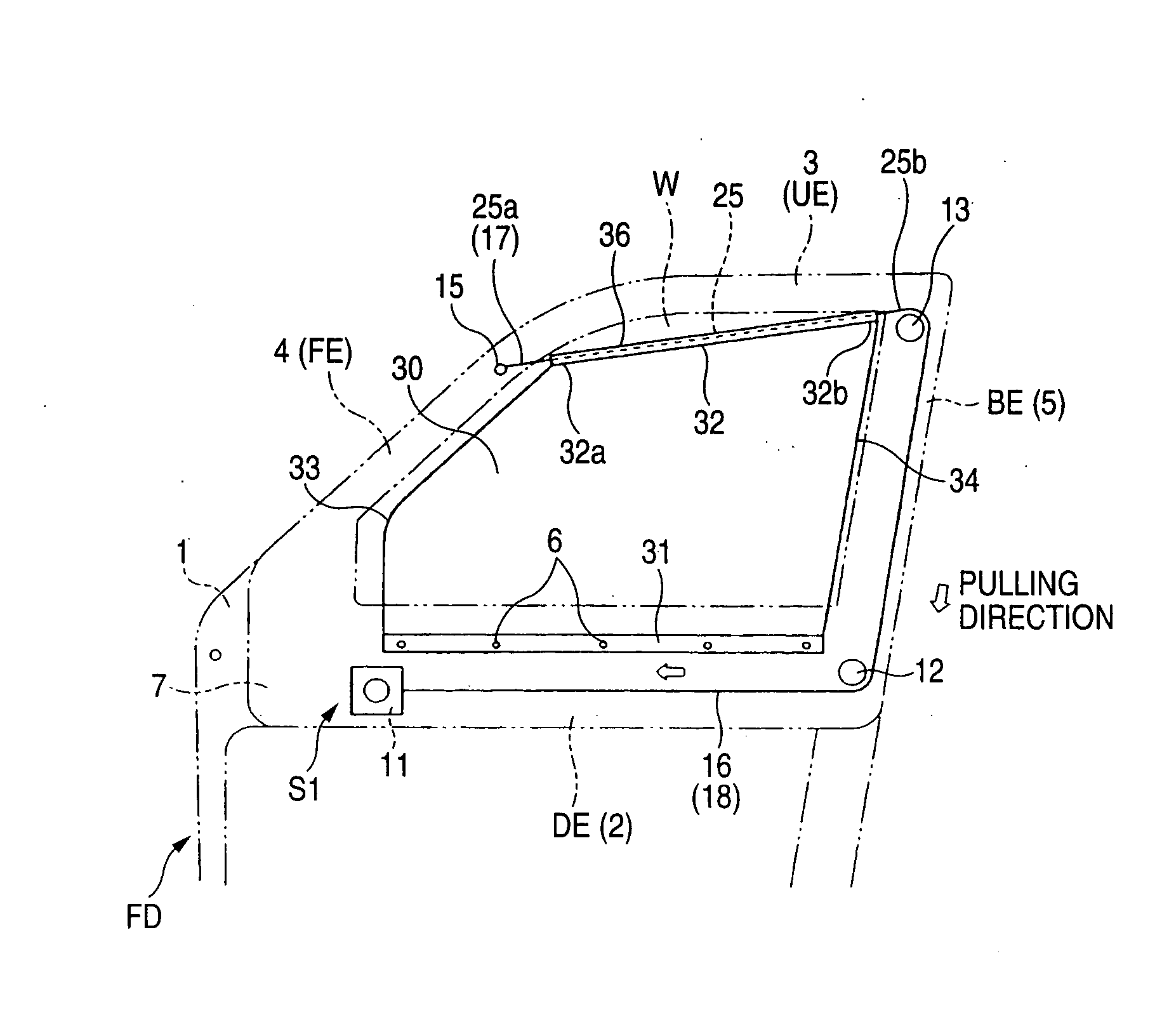
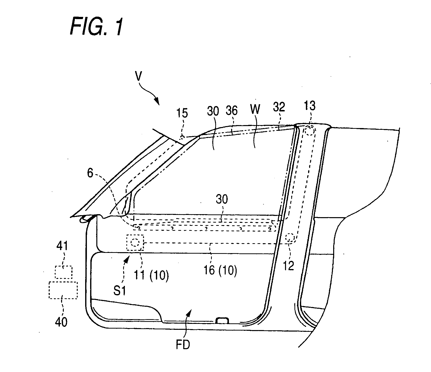
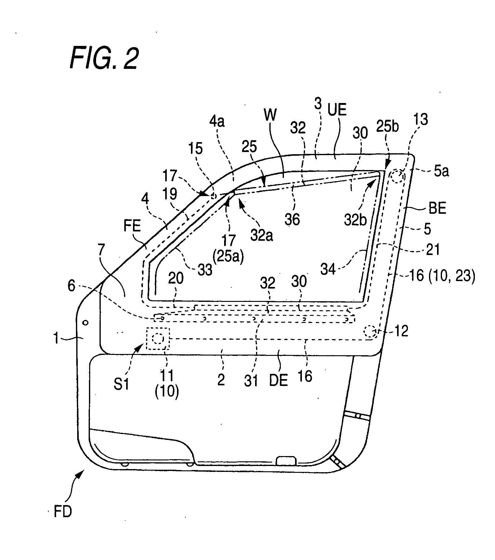
[0059] Hereinafter, embodiments of the invention will be described based on the accompanying drawings. As shown in FIGS. 1 to 3, an occupant protection apparatus S1 of a first embodiment includes a cover sheet 30 which is folded to be accommodated in a window (a side window) W of a vehicle V on a lower edge portion DE of a peripheral edge thereof and a pulling unit 10 which pulls up the cover sheet so as to cover the side window W. In the case of this embodiment, the side window W is provided in a front door FD of the vehicle V, and the cover sheet 30 and the pulling unit 10 are installed in the peripheral edge of the side window W.

[0060] In addition, this front door FD includes a door frame 1 which makes up the peripheral edge of the side window W, and a door trim 7 is mounted on an internal side of the door frame 1. The door frame 1 is provided with a front frame portion 4 which is situated on a front edge FF side of the peripheral edge of the side window W, a lower frame portion ...

third embodiment

[0087] In addition, when providing a stopper mechanism between the cover sheet and the pulling string, the occupant protection apparatus of the invention may be configured into an occupant protection apparatus S3 of a third embodiment in which two stopper mechanisms 43, 44 are provided as shown in FIGS. 12 to 15C. Namely, in addition to a first stopper mechanism 43 which is provided between a portion of a passageway portion 36C which lies toward a support member 13 and a pulling string 16C, a second stopper mechanism 44 is provided.

second embodiment

[0088] As shown in FIGS. 14 to 15C, similar to the second embodiment, the first stopper mechanism 43 is provided with a pulling block 27 secured to the pulling string 16C and a constricted portion 37a at a pulling source-end end portion 37. Namely, The pulling block 27 is formed of a metallic material or synthetic resin material which has rigidity and is formed into a conical shape which is diametrically expanded on a side which faces a fixed end 17 with an apex disposed on a side which faces the support member 13. The constricted portion 37a is formed into a tapered tubular shape which gradually reduces its diameter as it extends toward the support member 13 and which has an inside diameter which enables the passage of the pulling string 16C itself but disables the passage of the pulling block 27.

[0089] In addition, the second stopper mechanism 44 is provided with a control block 28 provided on the pulling string 16C and a non-return claw portion 38a provided on a fixed-end end por...


PUM


Abstract

An occupant protection apparatus includes a cover sheet adapted to be fed out from a peripheral edge of a window of a vehicle, when a pulling unit is activated, so as to cover the window. The pulling unit includes a pulling string having flexibility and a pulling device to which the pulling string is connected so as to be pulled thereby and which is disposed below the window. When the pulling device is activated, the pulling string is pulled such that a portion thereof which extends from a fixed end to where it is supported by a support member becomes a straight line while a portion thereof which is disposed along a lower edge portion of the peripheral edge of the window is caused to rise. The cover sheet includes a passageway portion through which the pulling string is passed on an upper side part thereof and is folded to be accommodated in the window only along the lower edge side of the peripheral edge thereof with the portion of the pulling string which has not yet been activated inserted into the passageway portion so as to be staying therein.

Description

BACKGROUND OF THE INVENTION [0001] 1. Related Art [0002] The present invention relates to an occupant protection apparatus in which a cover sheet is fed out of a peripheral edge of a window of a vehicle, when activated, so as to prevent an occupant from being ejected from the window of the vehicle when the vehicle rolls over (overturns). [0003] 2. Related Art [0004] As a conventional occupant protection apparatus, there exists an occupant protection apparatus in which a cover sheet is folded to be accommodated in a peripheral edge of a window of a vehicle such that the cover sheet is fed out thereof so as to cover the window when a pulling unit is activated to operate (for example, refer to JP-A-2002-19572). [0005] In this occupant protection apparatus, the pulling unit is provided with a pulling string which is connected to the cover sheet and a pulling device which pulls the pulling string. In addition, the pulling string extends downward from a fixed point on a front side of the ...

Claims


Application Information

Patent Timeline
Patent Type & Authority Applications(United States)
IPC IPC(8): B60J1/20
CPCB60J1/2025B60J1/2086B60R21/08B60R2021/0018
Inventor YAMAMURA, DAISUKEINOUE, MICHIO
Owner TOYODA GOSEI CO LTD
Why Eureka
Try Eureka