Method for producing battery electrode

a battery electrode and electrode technology, applied in the direction of cell components, final product manufacturing, sustainable manufacturing/processing, etc., can solve the problems of becoming more difficult for the binder near the current collector to rise to the surface region of the paste, so as to achieve efficient application and simplify the structure of the device

Inactive Publication Date: 2015-04-21
TOYOTA JIDOSHA KK
View PDF10 Cites 0 Cited by
  • Summary
  • Abstract
  • Description
  • Claims
  • Application Information

AI Technical Summary

Benefits of technology

[0013]In this case, the amount of binder near the current collector increases because the binder in the paste gathers near the current collector as a result of electrical attraction (electrostatic attraction). Moreover, the binder will be drawn toward the current collector by electrical attraction even if convection occurs during drying of the paste, and thus it becomes more difficult for the binder near the current collector to rise to the surface region of the paste. Accordingly, a suitable amount of binder is maintained near the current collector, and the adhesion between the active material layer that is obtained after drying and the current collector can be increased thereby.
[0014]In one preferred mode disclosed herein the above polymer material includes a first polymer that functions as a binder in the above active material layer and a second polymer that functions as a thickener in the above paste, and the above ionic polymer is used at least as the second polymer. In this case, the viscosity of the paste near the current collector increases because the thickener (second polymer) in the paste gathers near the current collector as a result of electrical attraction. As a result, the mobility of the binder (first polymer) near the current collector decreases, and therefore it becomes more difficult for the binder near the current collector to rise to the surface region of the paste even if convection occurs during drying of the paste. Accordingly, a suitable amount of binder is maintained near the current collector, and the adhesion between the active material layer that is obtained after drying and the current collector can be increased thereby.
[0017]In one preferred mode disclosed herein the solvent in the above paste is evaporated at a rate of 1 mL / s or higher per square meter of liquid surface area (i.e., 1 mL / s·m2 or higher). With the present invention, the solvent in the paste can be evaporated off rapidly since there is no need to account for migration-induced binder maldistribution when setting the drying rate of the paste, and therefore productivity increases dramatically.
[0020]In one preferred mode disclosed herein the above electric potential application means is a charge roller to which a voltage has been applied. An electric potential can be efficiently applied to the current collector by using a charge roller.
[0021]In one preferred mode disclosed herein the above current collector is a continuous sheet-shaped current collector. Moreover, the electric potential application means is a roller conveyor that conveys the sheet-shaped current collector in a lengthwise direction thereof. With this configuration, a roller conveyor can be used as the electric potential application means, so the structure of the device can be simplified.
[0023]The present invention further provides a battery (e.g., a lithium secondary battery) constructed using an electrode obtained by any of the methods disclosed herein. This battery is constructed using the electrode with superb adhesion of the active material layer to the current collector as described above for at least one of the electrodes and therefore exhibits excellent battery performance. For example, a battery featuring at least one characteristic from among excellent output characteristics, high durability, and good productivity can be provided by constructing the battery using the above electrode.

Problems solved by technology

Moreover, the binder will be drawn toward the current collector by electrical attraction even if convection occurs during drying of the paste, and thus it becomes more difficult for the binder near the current collector to rise to the surface region of the paste.
As a result, the mobility of the binder (first polymer) near the current collector decreases, and therefore it becomes more difficult for the binder near the current collector to rise to the surface region of the paste even if convection occurs during drying of the paste.

Method used


Image

  • Method for producing battery electrode
  • Method for producing battery electrode
  • Method for producing battery electrode

Examples


embodiment 1

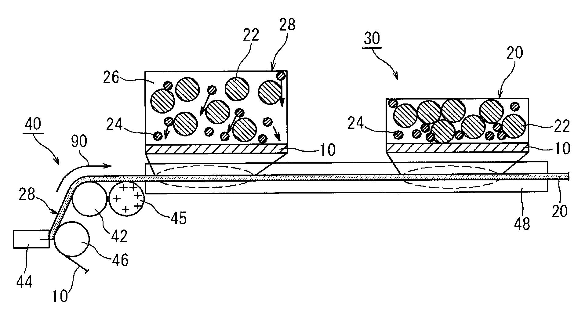
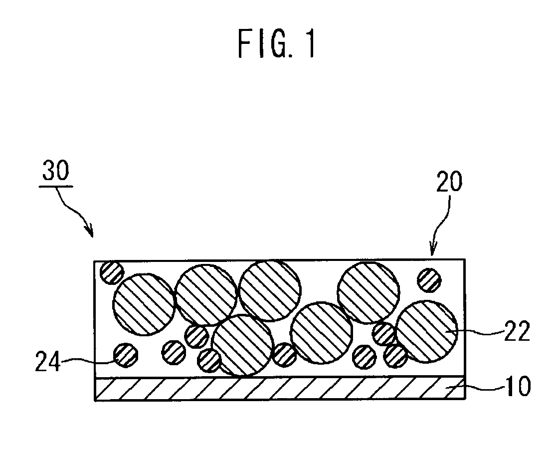
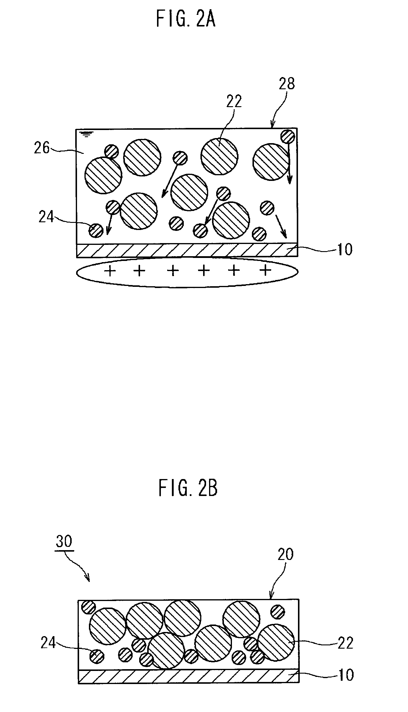
[0035]The method for producing a battery electrode disclosed herein is a method for producing an electrode 30 having a configuration in which an active material layer 20 containing an active material 22 and a polymer material 24 is retained on a current collector 10, as shown in FIG. 1. This method comprises a step wherein a paste for forming an active material layer 28 containing the active material 22 and the polymer material 24 in a solvent 26 is applied to the current collector 10, as shown in FIG. 2A, and a step wherein the active material layer 20 is formed on the current collector 10 by drying the applied paste 28, as shown in FIG. 2B.

[0036]Here an ionic polymer 24 exhibiting cationic or anionic properties in the above paste is used as at least one kind of the above polymer material, and an electric potential having an opposite polarity to that of the ionic polymer 24 is applied to the current collector 10 after the paste has been applied thereto. The ionic polymer in this em...

embodiment 2

[0055]In the above embodiment a case is described wherein the ionic polymer functions as a binder in the active material layer, but the present invention is not limited thereto. For example, the ionic polymer can function as a thickener in the paste instead of or in addition to its function as a binder.

[0056]In other words, as shown in FIG. 4A, in this embodiment the polymer material comprises a first polymer 124 that functions as a binder in the active material layer 120 and a second polymer 125 that functions as a thickener in the paste, and an ionic polymer is used at least as the second polymer (thickener) 125. An electric potential opposite to that of the second polymer (thickener) 125 is then applied to the current collector 110 after the paste has been applied thereto.

[0057]The second polymer (thickener) 125 in this embodiment is an anionic polymer having a carboxyl group and, for example, carboxymethyl cellulose (CMC) can be used therefor. Moreover, the first polymer (binder...

example 1

[0062]In this example, a paste for forming an active material layer 28 was prepared by dispersing graphite powder as the negative electrode active material 122 and carboxylated styrene-butadiene rubber (XSBR) as the ionic polymer (binder) in water such that the mass ratio of these ingredients was 99:1. This paste for forming an active material layer 28 was applied to one side of a continuous sheet-shaped copper foil (current collector 22) such that the thickness thereof was 100 μm, and the negative electrode sheet 30 with a negative electrode active material layer 20 formed on a current collector 10 was obtained by applying a positive charge of approximately 2.4 V to the current collector using a charge roller and then drying with a hot air flow at approximately 120° C. for 20 seconds. It should also be noted that the solid content ratio of the paste for forming the active material layer was adjusted to approximately 50%. Moreover, XSBR having carboxyl groups on the order of roughly...


PUM

PropertyMeasurementUnit
electric potentialaaaaaaaaaa
temperatureaaaaaaaaaa
thicknessaaaaaaaaaa

Abstract

The present invention provides a method for producing a battery electrode having a configuration in which an active material layer containing an active material 22 and a polymer material 24 is retained on a current collector 10, the method comprising a step of applying a paste for forming an active material layer 28 containing the active material 22 and the polymer material 24 in a solvent 26, to the current collector 10, and a step of forming an active material layer on the current collector 10 by drying the applied paste 28. An ionic polymer exhibiting cationic or anionic properties in the paste 28 is used as at least one kind of the polymer material 24, and an electric potential having an opposite polarity to that of the ionic polymer 24 is applied to the current collector 10 after the paste 28 has been applied to the current collector 10.

Description

CROSS-REFERENCE TO RELATED APPLICATIONS[0001]This application is a national phase application of International Application No. PCT / JP2009 / 069539, filed Nov. 18, 2009, the contents of which are incorporated herein by reference.TECHNICAL FIELD[0002]The present invention relates to a method for producing a battery electrode, and more particularly to a method for producing a battery electrode having a configuration in which an electrode active material layer containing an electrode active material is retained on a current collector.BACKGROUND ART[0003]Lithium ion batteries, nickel-metal hydride batteries, and other secondary batteries have become more important recently as vehicle-mounted electrical power sources, and as power sources for personal computers and portable devices. In particular, it is expected that lithium secondary batteries that are light weight and provide high energy density can be preferably used as a high-output electric power source for vehicles. One typical config...

Claims


Application Information

Patent Timeline
Patent Type & Authority Patents(United States)
IPC IPC(8): H01M4/13H01M4/82H01M4/131H01M4/137H01M4/139H01M4/1399H01M4/60H01M4/62H01M4/66H01M10/052
CPCH01M4/0404H01M4/0438H01M4/131H01M4/137H01M4/1399H01M4/60H01M4/602H01M4/622H01M4/661H01M10/052Y02E60/122Y02T10/7011Y10T29/49115Y02E60/10Y02P70/50Y02T10/70
Inventor NAKANO, TAKAHIKO
Owner TOYOTA JIDOSHA KK
Why Eureka
Try Eureka