Wiring of touch panel

a touch panel and wire technology, applied in the field of touch panels, can solve the problems of increasing screen cost, occupying a large room, and increasing manufacturing tim

Inactive Publication Date: 2007-05-10
TRENDON TOUCH TECHNOLOGY CORPORATION
View PDF7 Cites 32 Cited by
  • Summary
  • Abstract
  • Description
  • Claims
  • Application Information

AI Technical Summary

Benefits of technology

[0009] After considerable research and experimentation, a new way of wiring of touch panel has been devised so as to overco

Problems solved by technology

This new requirement does not leave much of a room to layout wires on the. edges of the touch screen creating new design challenges.
This would increase the manufacturing time and the complication therefore would also increase the screen cost.
However, this invention does not address the conductive buses issue.
These buses increase the size of the screen.
However, conductive busses that carry the current to the four corners of the touch panel are still placed on the screen and these buses increase the width of the screen.
However, this technique may increase the wire resistance.
This might interfere with signal transmission.
It is also more difficult and less economical to produce touch panels with narrow

Method used


Image

  • Wiring of touch panel
  • Wiring of touch panel
  • Wiring of touch panel

Examples


Embodiment Construction

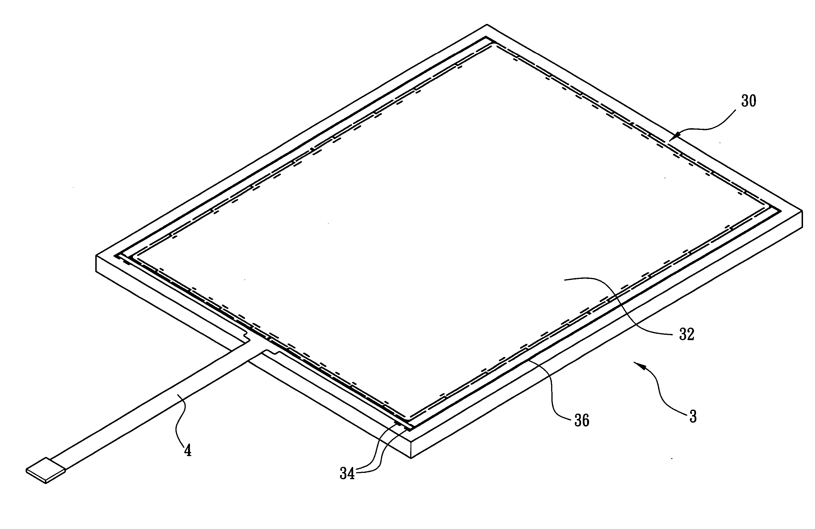
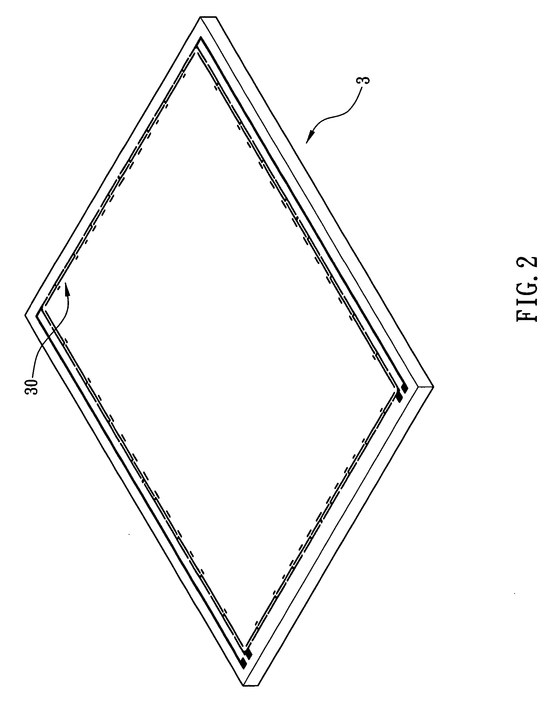
[0022] Referring to FIGS. 2 and 3, a wiring of touch panel in accordance with the first preferred embodiment of the invention is shown. A transparent and conductive layer (not shown) is placed on the top surface of a glass substrate 3. A plurality of wires 30 are provided along the border between the edge of the transparent and the conductive layer and the transparent operating area 32. A flexible circuit board 4 is placed at one side of the transparent and conductive layer and the wires 30. The flexible circuit board 4 is extended beyond the glass substrate 3 and is electrically connected to a control circuit. The conductive end 34 is formed at the transparent and conductive layer between each of the wires 30 and the flexible circuit board 4. By using this technique, the plurality of parallel conductors of prior art are replaced by the flexible circuit board 4. This decreases the wiring area requirement. As a result, it is possible to produce touch panels with narrower border than ...


PUM


Abstract

The present invention is to provide a wiring of a touch panel comprising a glass substrate including a transparent and conductive layer on a top surface; a plurality of wires disposed along a border of the glass substrate; a plurality of conductive ends formed at the top side of the glass substrate, each of the wires being electrically connected to one of the conductive ends; and a flexible circuit board provided at the wires, the flexible circuit board including a plurality of connections each electrically connected to one of the conductive ends. By utilizing this wiring, prior used conductors are replaced by the flexible circuit board in order to decrease wiring area and make wiring of the touch panel become narrower.

Description

FIELD OF THE INVENTION [0001] The present invention relates to touch panels, more particularly a touch panel utilizing a flexible circuit board to replace conductors on a glass substrate thereof, or move the conductors to a bottom surface of the glass substrate in order to decrease the wiring area and make the wiring area of the touch panel narrower than the touch panels that are manufactured using the current state of the art. BACKGROUND OF THE INVENTION [0002] Recently, conventional input devices (e.g. keyboards and mouse) are being replaced with touch panels as the choice of human-machine interface devices. These human-machine interface devices are widely used in various electronic products (e.g., GPSs (Global Positioning Systems), PDAs (personal digital assistants), cellular phones, and hand-held PCs). Touch panels provide direct and better user interface while eliminating the need for the conventional input devices. The space that is saved by eliminating the conventional input ...

Claims


Application Information

Patent Timeline
IPC IPC(8): G09G5/00
CPCG06F3/045
Inventor CHIEN, SHUN-TACHEN, SHIH-CHING
Owner TRENDON TOUCH TECHNOLOGY CORPORATION
Why Eureka
Try Eureka