Optical network system and device, and method for controlling optical network and device

a technology of optical network and optical network device, which is applied in the direction of bus-type electromagnetic network, multi-component communication, digital transmission, etc., can solve the problems of the inability to remove the deviation of the time length or phase of the pulse, etc., to achieve the effect of suppressing the deviation in width

Inactive Publication Date: 2007-05-10
TOKYO ELECTRON DEVICE
View PDF5 Cites 6 Cited by
  • Summary
  • Abstract
  • Description
  • Claims
  • Application Information

AI Technical Summary

Benefits of technology

[0014] Another object of the present invention is to suppress deviation in width (time length) and / or the phase of pulse of the transmitting signal.

Problems solved by technology

However, when the transmission of a pulse representing data is executed in synchronization with the clock, there will be a problem with the deviation of time length or phase of the pulse, as the pulse is latched under an unstable state of pulse transition or the like.
Despite of employing the above mentioned method using a stack, however, a problem with the deviation of the time length or phase of a pulse has been generated due to the jitter of the clock signal or fluctuation of frequency.
In addition, making the time length of a pulse representing data as long as possible to withstand practical use has not been successful in removing the effect of the deviation of the time length or phase of a pulse.

Method used


Image

  • Optical network system and device, and method for controlling optical network and device
  • Optical network system and device, and method for controlling optical network and device
  • Optical network system and device, and method for controlling optical network and device

Examples


Embodiment Construction

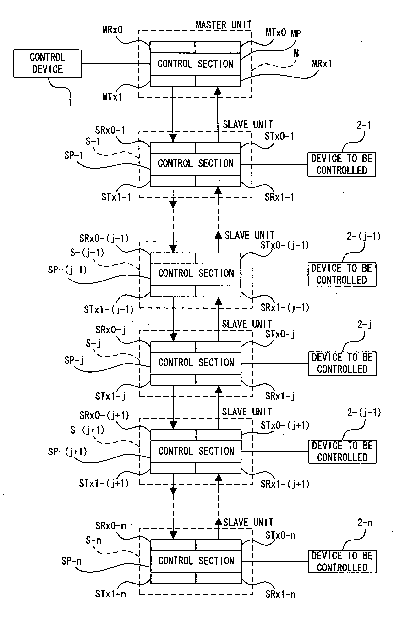
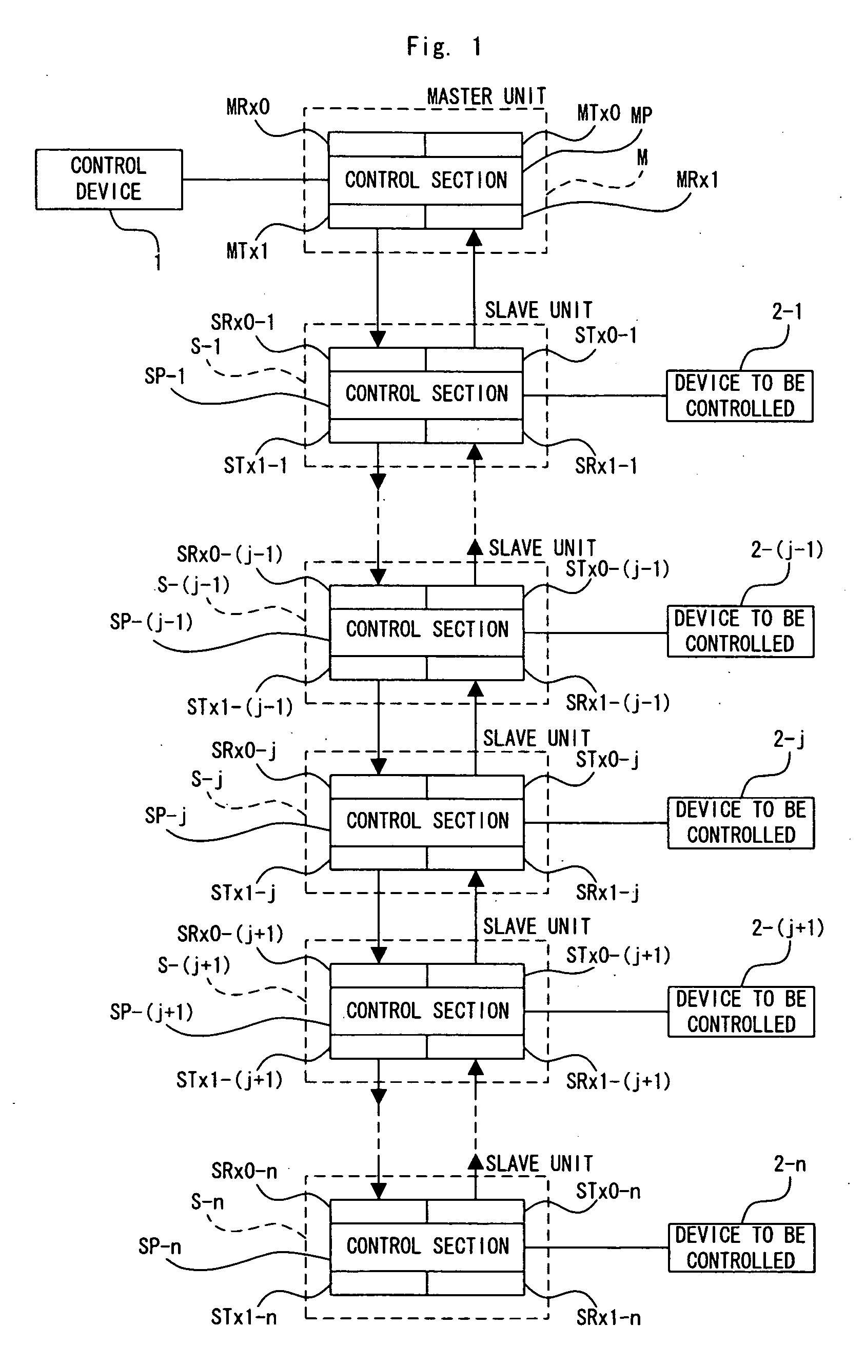
[0083] An embodiment of the present invention is explained below taking an optical network system as an example and referring to the drawings.

[0084] As shown in FIG. 1, this optical network system comprises a master unit M and slave units S-1 to S-n of n-pieces (n represents an integer greater than 1).

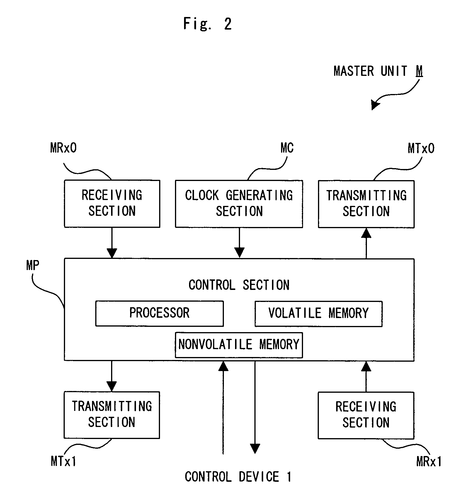
[0085] The master unit M comprises a control section MP, a clock generating section MC, transmitting sections MTx0 and MTx1, and receiving sections MRx0 and MRx1, as shown in FIG. 2. The clock generating section MC, transmitting sections MTx0 and MTx1, and receiving section MRx0 and MRx1 are connected to the control section MP electrically.

[0086] The slave units S-1 to S-n have substantially the same structure and functions with each other. The slave unit S-k (k represents an integer equal to or greater than 1, and equal to or less than n) comprises a control section SP-k, a clock generating section SC-k, transmitting sections STx0-k, and STx1-k, and receiving sections SRx0-k, and S...


PUM


Abstract

When entering an idling state, a master unit M transmits an optical signal for polling addressed to each slave unit S-1 to S-n. The slave unit S-n located at the lowest rank of a direct chain constituted by S-1 to S-n, when receiving the optical signal for polling for the self unit, responds by transmitting an optical signal representing a phase correction request signal to the other slave units. The slave units S-1 to S-(n−1) respond to the phase correction request signal, and initialize each clock signal to synchronize with the clock signal of the slave unit S-n at the lowest rank.

Description

BACKGROUND OF THE INVENTION [0001] 1. Field of the Invention [0002] The present invention relates to an optical network system, optical network device and optical network control method to execute data communication through an optical network. [0003] 2. Description of the Related Art [0004] Recently, data communication through an optical network has been popularized with the purpose of remote control of electrical equipment. To execute data communication through an optical network between one piece of equipment as a master unit and multiple pieces of equipment as slave units, as published in Unexamined Japanese Patent Application KOKAI Publication No. H8-147229 for example, this equipment is interconnected in the shape of a so called multi-drop connection to execute data communication. The disclosure of the Unexamined Japanese Patent Application KOKAI publication No. H8-147229 is incorporated herein by reference in its entirety. [0005] For this multi-drop connection, an order is pre...

Claims


Application Information

Patent Timeline
Patent Type & Authority Applications(United States)
IPC IPC(8): H04J14/00H04B10/27H04B10/278H04L7/00H04L12/28
CPCH04J3/0638H04J3/08
Inventor HIRAKA, SEIJI
Owner TOKYO ELECTRON DEVICE
Why Eureka
Try Eureka