Optical regenerator in optical fiber communication system
- Summary
- Abstract
- Description
- Claims
- Application Information
AI Technical Summary
Benefits of technology
Problems solved by technology
Method used
Image
Examples
embodiment 1
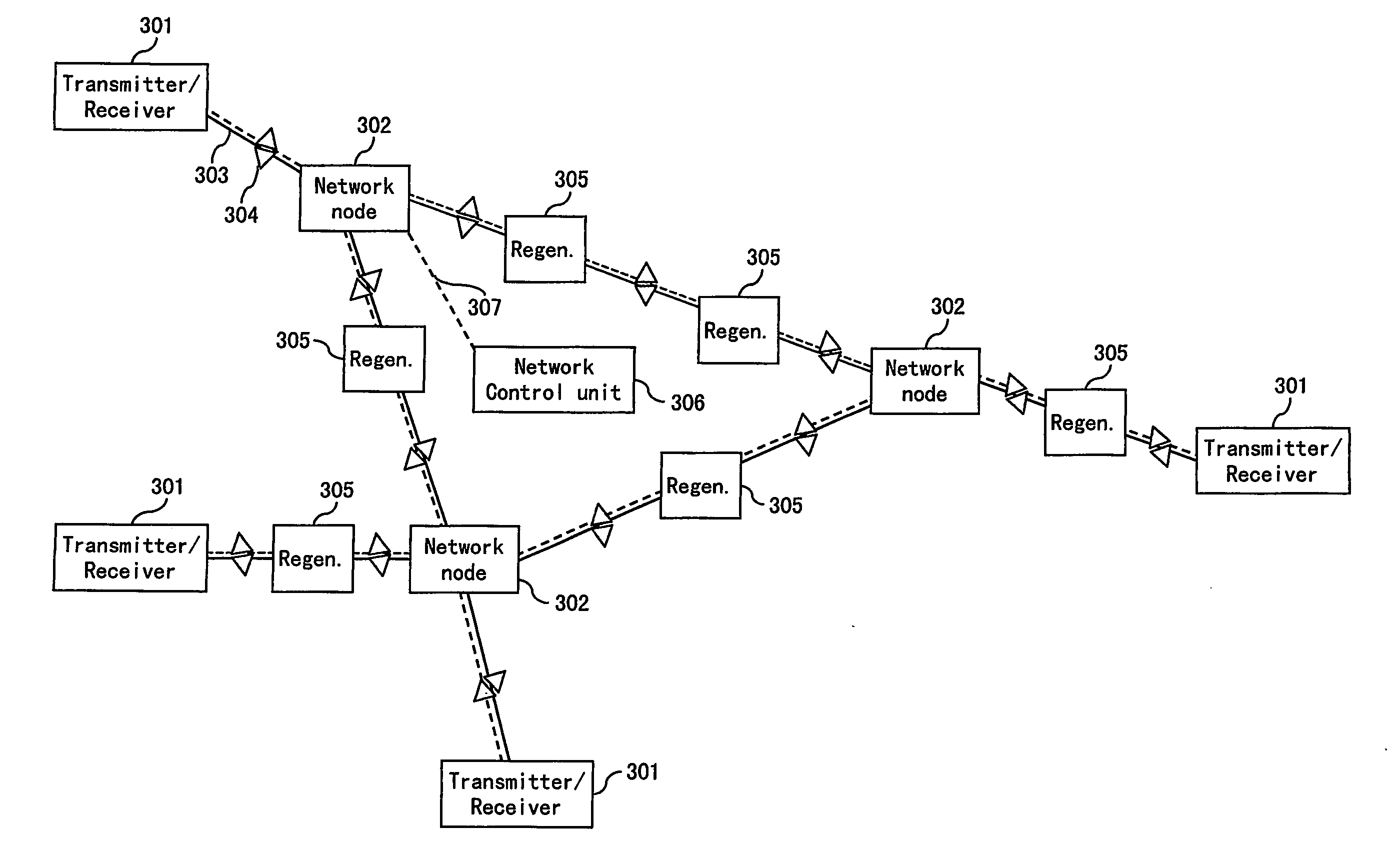
[0061] In the first preferred embodiment shown in FIGS. 8 and 9, the monitoring devices 406 and 407 comprise photodiodes 801 and 802, respectively, for measuring the optical power levels. The electrical signal of the first photodiode 801 is used to adjust the input power to the nonlinear device 403 to a preset value. The electrical signal of the second photodiode 802 is used to adjust the output power of the regenerator to a preset value. The control unit 408 carries out the adjustments and communicates with a central network control unit or other regenerator nodes via the optical supervisory channel 409.
[0062] The target value for the optical input power to the nonlinear device 403 is preset at the time of installation of the system as a target value of the average input power detected by the first photodiode 801. The optimum target value has to be determined at the time of installation. There are two preferred methods:
[0063] a) The BER is monitored with a BER measurement equipme...
embodiment 2
[0069] In the second preferred embodiment, each regenerator shown in FIGS. 8 and 9 is replaced with a regenerator as shown in FIG. 10 and the optical communication system is configured as shown in FIG. 11. The BER measurement equipment is not required. In this case, the monitoring device 406 comprises a photodiode 801, and the monitoring device 407 comprises a photo diode 802, an optical coupler 1001, and a signal quality monitor 1002. The electrical signal of the first photodiode 801 is used to adjust the input power to the nonlinear device 403 to a preset value. The signal light tapped by the optical coupler 405 branches at the optical coupler 1001 to the photodiode 802 and the signal quality monitor 1002. The electrical signal of the second photodiode 802 is used to adjust the output power of the regenerator to a preset value. The signal quality monitor 1002 monitors the signal quality (BER, the minimum of the pdf, etc.) of the output signal light of the regenerator. The control ...
embodiment 3
[0071] In the third preferred embodiment, the monitoring devices 406 comprises a photodiode 801 for measuring the optical power, an optical coupler 1101, and a signal quality monitor 1102, and the monitoring device 407 comprises a photodiode 802 as shown in FIGS. 12 and 13. The signal light tapped by the optical coupler 402 branches at the optical coupler 1101 to the photodiode 801 and the signal quality monitor 1102. The electrical signal of the first photodiode 801 is used to adjust the input power to the nonlinear device 403 to a preset value. The electrical signal of the second photodiode 802 is used to adjust the output power of the regenerator to a preset value. The signal quality monitor 1102 monitors the signal quality of the input signal light to the nonlinear device 403. The control unit 408 carries out the adjustments. The adjustment of the optical input power to the nonlinear device 403 can be carried out during the operation of the optical communication system in two wa...
PUM
 Abstract
Description
Claims
Application Information
 - R&D
- Intellectual Property
- Life Sciences
- Materials
- Tech Scout
- Unparalleled Data Quality
- Higher Quality Content
- 60% Fewer Hallucinations
Browse by: Latest US Patents, China's latest patents, Technical Efficacy Thesaurus, Application Domain, Technology Topic, Popular Technical Reports.
© 2025 PatSnap. All rights reserved.Legal|Privacy policy|Modern Slavery Act Transparency Statement|Sitemap|About US| Contact US: help@patsnap.com


