Radio control flying toy

Inactive Publication Date: 2007-05-10
TAIYO KOGYO CORPORATION
View PDF20 Cites 100 Cited by
  • Summary
  • Abstract
  • Description
  • Claims
  • Application Information

AI Technical Summary

Benefits of technology

[0014] In the present invention, the operation button has four operation buttons corresponding to the first to fourth driving means for front, back, left, and right, respectively. The running can be easily controlled by the operations of four operation buttons.
[0015] In the present invention, the radio control flying toy is provided with: the airframe formed into the rectangular plate shape having the bottom surface which is flat on the lower side; the first to fourth propellers which are disposed in the four corners forming at least the quadrangular shape on the lower side of the airframe and which feed the air to the bottom-surface side to float the airframe; the first to fourth driving means for driving the firs

Problems solved by technology

Therefore, a large driving power supply is required for driving the blower for flying or propelling,

Method used


Image

  • Radio control flying toy
  • Radio control flying toy
  • Radio control flying toy

Examples


first embodiment

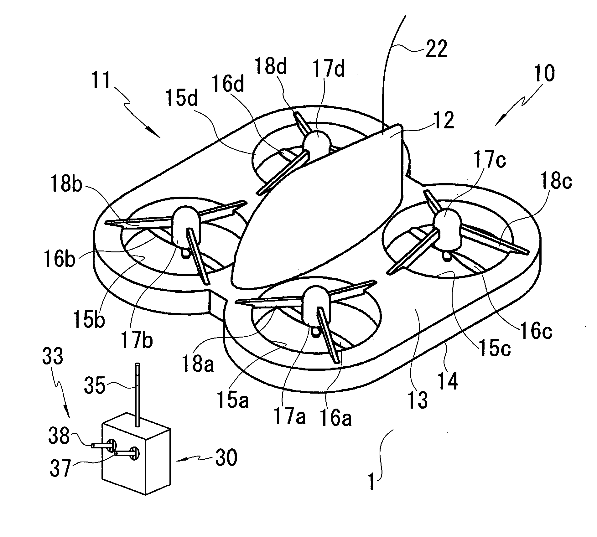
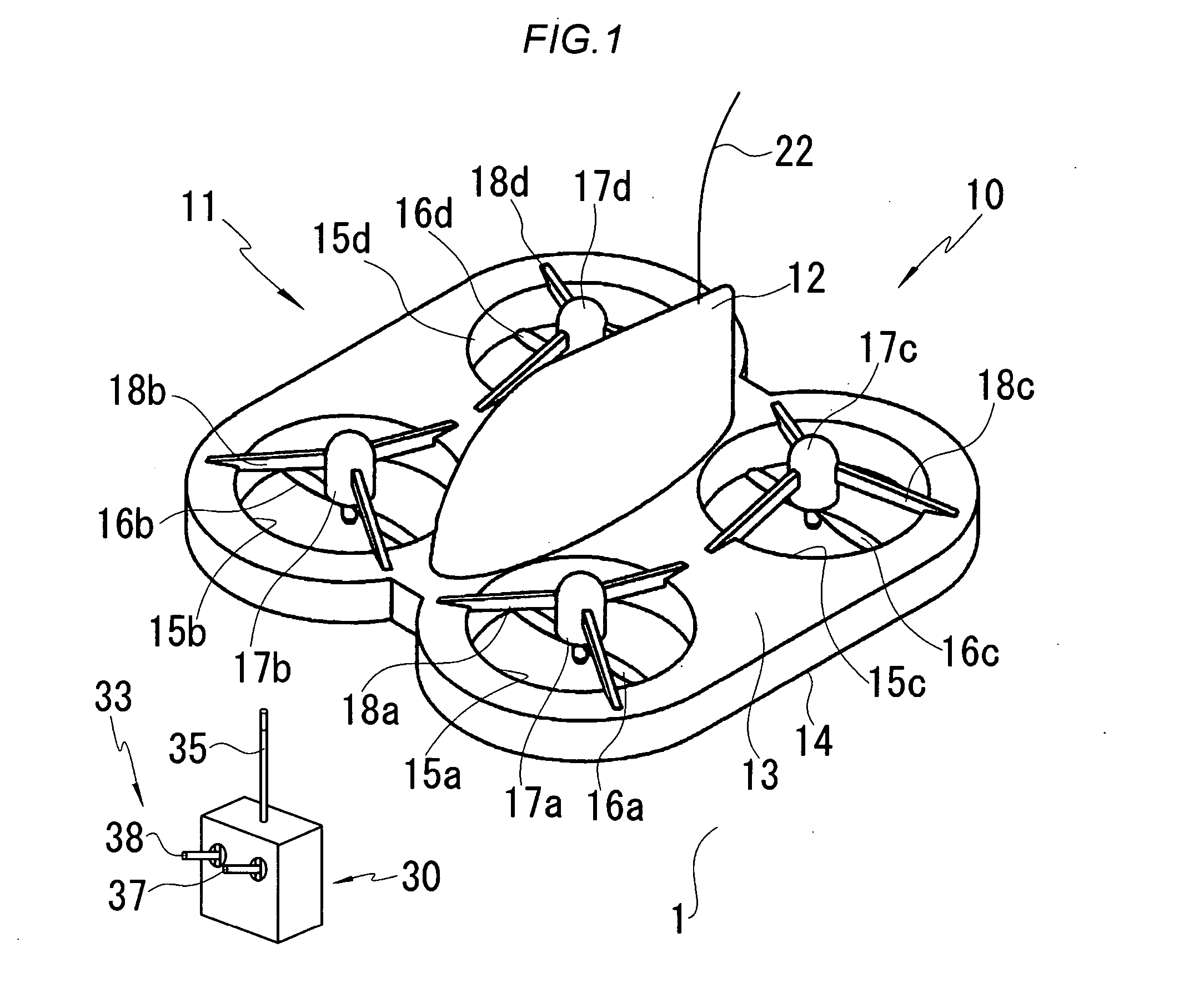
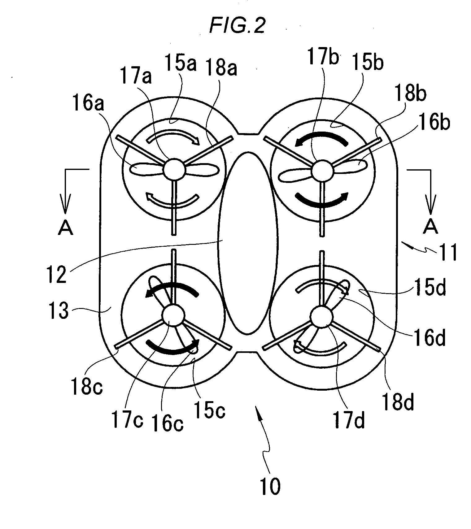
[0037] One embodiment of the present invention will be described hereinafter in more detail with reference to the drawings. FIGS. 1 to 7 are explanatory views of a constitution of a radio control flying toy in the present invention. FIG. 1 is a perspective view of the radio control flying toy; FIG. 2 is a plan view of the radio control flying toy; FIG. 3 is a sectional view along line A-A of the radio control flying toy of FIG. 2; FIG. 4 is a back view of the radio control flying toy; FIG. 5 is a side view of the radio control flying toy; FIG. 6 is a bottom plan view of the radio control flying toy; and FIG. 7 is a block diagram showing a control operation of the radio control flying toy.

[0038] In these drawings, in the first embodiment of the present invention, a radio control flying toy 10 is a flying toy which can be enjoyed by floating and freely flying the toy above a flat running surface 1 such as a ground or water surface in the outdoor, or a floor surface in the indoor. This...

second embodiment

[0052] Next, an operation of the radio control flying toy 40 constituted as described above will be described. FIGS. 17 to 21 are explanatory views of the operation of the radio control flying toy in the FIG. 17 is an explanatory view of an operation of a transmitter at a time when the radio control flying toy floats; FIG. 18 is an explanatory view of an operation of the transmitter at a time when the radio control flying toy moves forwards; FIG. 19 is an explanatory view of an operation of the transmitter at a time when the radio control flying toy moves backwards; FIG. 20 is an explanatory view of an operation of the transmitter at a time when the radio control flying toy swivels clockwise; and FIG. 21 is an explanatory view of an operation of the transmitter at a time when the radio control flying toy swivels counterclockwise.

[0053] First, to operate the radio control flying toy 40, when a power switch 19 is turned on, all of the first to fourth driving means 17a, 17b, 17c, and ...


PUM


Abstract

There is disclosed a radio control flying toy in which an airframe can be easily floated and a running direction can be easily controlled. The toy is provided with: an airframe 11 formed into a rectangular plate shape having a flat bottom surface on a lower side; first to fourth propellers 16a, 16b, 16c, and 16d which are disposed in four corners forming at least a quadrangular shape on the lower side of the airframe 11 and which feed air toward a bottom-surface side to float the airframe 11; first to fourth driving means 17a, 17b, 17c, and 17d which drive the first to fourth propellers 16a, 16b, 16c, and 16d, respectively; a control unit 20 which individually controls driving outputs of the first to fourth driving means 17a, 17b, 17c, and 17d, respectively; a transmitter 30 for transmitting a control signal for flight from the outside to the control unit 20; and a battery 21 which supplies power to the first to fourth driving means 17a, 17b, 17c, and 17d and the control unit 20.

Description

BACKGROUND OF THE INVENTION [0001] 1. Field of the Invention [0002] The present invention relates to a radio control flying toy which can feed air to an airframe on a bottom-surface side to float the airframe along a flat running plane, thereby freely flying the airframe. [0003] 2. Description of the Related Art [0004] Heretofore, Hovercraft (trade name), an air cushion vehicle or the like has been generally known as a ground effect machine or a vehicle which travels utilizing a lift force of an air cushion contained between a bottom surface of an airframe and a running surface such as a ground or water surface on a lower side, or ground effects of wings. As a toy which travels under remote control utilizing a principle of such ground effect machine, the present applicant discloses a technology concerning an air cushion toy in which a skirt portion formed into an expandable / contractible bag shape is attached to a lower peripheral edge of a main body, and air is sucked from the outsi...

Claims


Application Information

Patent Timeline
IPC IPC(8): A63H27/127
CPCA63H27/02A63H27/12A63H30/04
Inventor GOTOU, TAKEOOOE, YOSHIAKI
Owner TAIYO KOGYO CORPORATION
Why Eureka
Try Eureka