Medical ultrasound system and handpiece and methods for making and tuning

a technology of ultrasound system and handpiece, applied in the field of medical equipment, can solve the problems of unsuitable for surgeons to hold and use in precise and delicate surgery, and achieve the effects of small size, large vibrational amplitude, and high displacemen

Active Publication Date: 2007-05-10
CILAG GMBH INT
View PDF40 Cites 136 Cited by
  • Summary
  • Abstract
  • Description
  • Claims
  • Application Information

AI Technical Summary

Benefits of technology

[0019] Several benefits and advantages are obtained from one or more of the expressions of embodiments of the invention. In one example, one or more or all of the expressions of embodiments of the invention help enable a relatively small size medical ultrasound transducer assembl

Problems solved by technology

Conventional medical ultrasound systems provide the instrument with a desirable high displacement (i.e., a large vibrational amplitude) by employing a relatively

Method used


Image

  • Medical ultrasound system and handpiece and methods for making and tuning
  • Medical ultrasound system and handpiece and methods for making and tuning
  • Medical ultrasound system and handpiece and methods for making and tuning

Examples


first embodiment

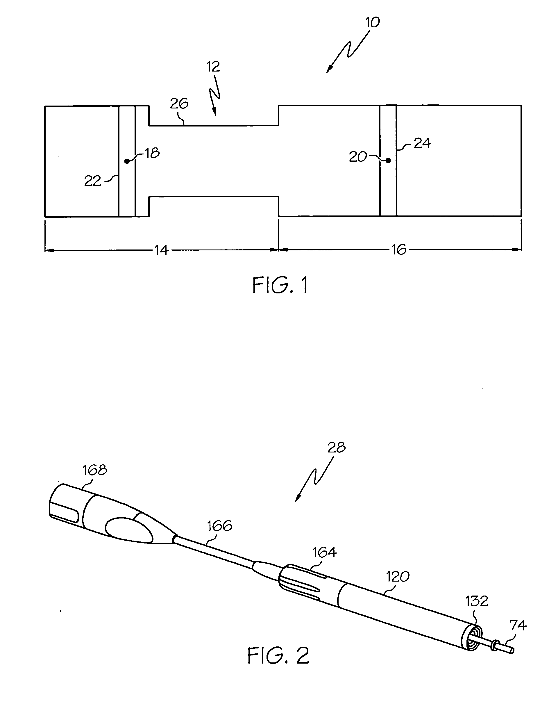
[0058] the invention is shown in FIG. 1. A first expression of the embodiment of FIG. 1 is for a medical ultrasound handpiece 10 including a medical ultrasound transducer assembly 12. The transducer assembly 12 includes consecutive first and second half-wave sections 14 and 16, wherein the first half-wave section 14 includes a first node 18 and the second half-wave section 16 includes a second node 20. The first half-wave section 14 includes a first piezoelectric transducer disk 22 substantially centered about the first node 18, and the second half-wave section 16 includes a second piezoelectric transducer disk 24 substantially centered about the second node 20. The transducer assembly 12 includes a gain stage 26 disposed between the first and second piezoelectric transducer disks 22 and 24.

[0059] It is noted, for the purpose of describing the various embodiments of the invention, that a medical ultrasound transducer assembly is a transducer assembly which ultrasonically vibrates an...

second embodiment

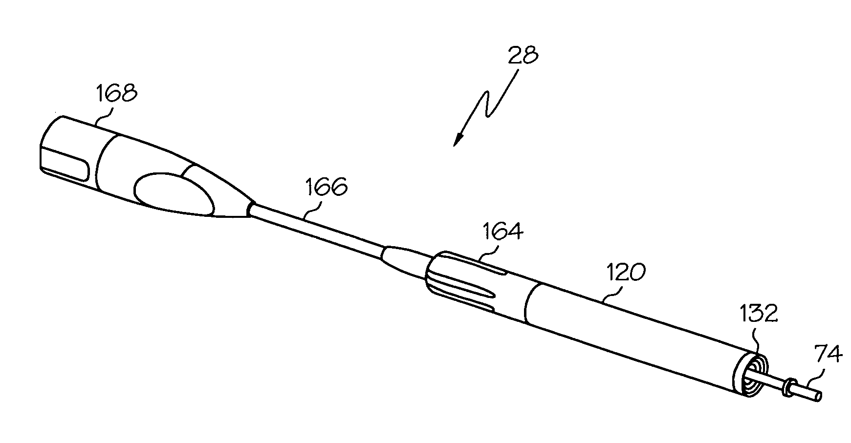
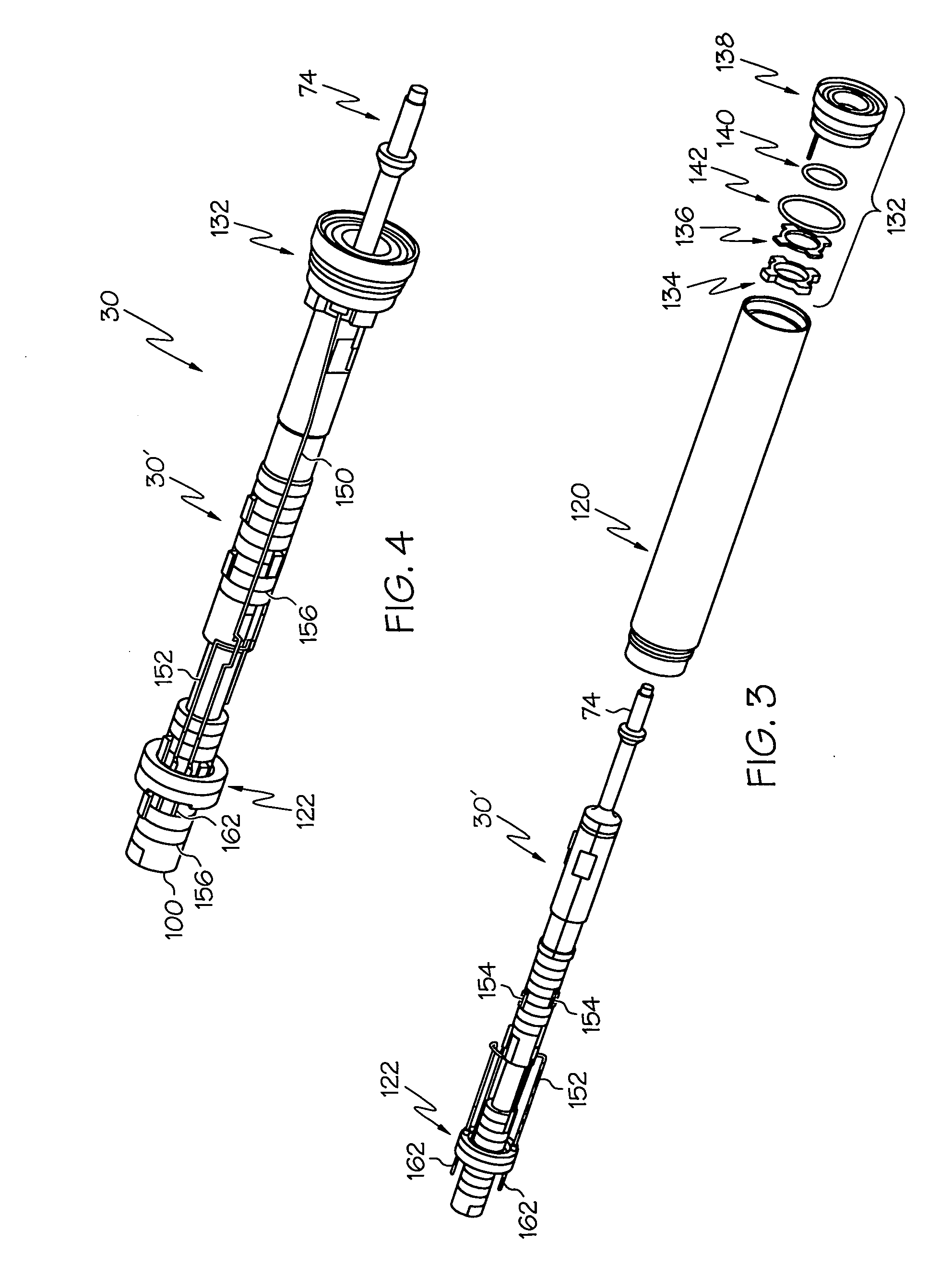
[0060] the invention is shown in FIGS. 2-13. A first expression of the embodiment of FIGS. 2-13 is for a medical ultrasound handpiece 28 including a medical ultrasound transducer assembly 30. The transducer assembly 30 includes consecutive first and second half-wave sections 32 and 34, wherein the first half-wave section 32 includes a first node 36 and the second half-wave section 34 includes a second node 38. The first half-wave section 32 includes a first stacked plurality 40 of piezoelectric transducer disks 42 substantially centered about the first node 36, and the second half-wave section 34 includes a second stacked plurality 44 of piezoelectric transducer disks 42 substantially centered about the second node 38. The transducer assembly 30 includes a gain stage 46 (also called a first gain stage) disposed between the first and second stacked pluralities 40 and 44 of piezoelectric transducer disks 42.

[0061] It is noted that, in one example, an electrode is disposed between adja...

third embodiment

[0084] the invention is shown in FIG. 15. A first expression of the embodiment of FIG. 15 is for a medical ultrasound handpiece 210 including a 1-wave medical ultrasound transducer assembly 212. The transducer assembly 212 includes consecutive first and distal-most second half-wave sections 214 and 216, wherein the first half-wave section 214 includes a first node 218 and the second half-wave section 216 includes a second node 220. The first half-wave section 214 includes a first stacked plurality 222 of piezoelectric transducer disks 224 and the second half-wave section 216 includes a second stacked plurality 226 of piezoelectric transducer disks 224. The transducer assembly 212 includes first and second gain stages 228 and 230, wherein the first gain stage 228 is located in the first half-wave section 214 distal the first stacked plurality 222 of piezoelectric transducer disks 224, and wherein the second gain stage 230 is located in the second half-wave section 216 distal the seco...


PUM


Abstract

Several embodiments of medical ultrasound handpieces are described each including a medical ultrasound transducer assembly. An embodiment of a medical ultrasound system is described, wherein the medical ultrasound system includes a medical ultrasound handpiece having a medical ultrasound transducer assembly and includes an ultrasonically-vibratable medical-treatment instrument which is attachable to a distal end of the transducer assembly. An embodiment of a medical ultrasound system is described, wherein the medical ultrasound system has a handpiece including a medical ultrasound transducer assembly and including a housing or housing component surrounding the transducer assembly. A method for tuning a medical ultrasound handpiece includes machining at least a distal non-threaded portion of an instrument-attachment stud of the transducer assembly to match a measured fundamental frequency to a desired fundamental frequency to within a predetermined limit. A method for making a medical ultrasound transducer assembly determines acceptable gains for gain stages of the transducer assembly.

Description

CROSS REFERENCE TO RELATED APPLICATIONS [0001] The present application claims the priority benefit of U.S. provisional patent application Ser. No. 60 / 726,625, filed on Oct. 14, 2005.FIELD OF THE INVENTION [0002] The present invention is related generally to medical equipment, and more particularly to a medical ultrasound handpiece having a medical ultrasound transducer assembly, to a method for tuning the handpiece, to a method for making the transducer assembly, and to a medical ultrasound system including a handpiece and an ultrasonically-vibratable medical-treatment instrument which is attachable to the distal end portion of the transducer assembly of the handpiece. BACKGROUND OF THE INVENTION [0003] Medical ultrasound systems are known which include a medical ultrasound handpiece having a medical ultrasound transducer assembly and which include an ultrasonically-vibratable medical-treatment instrument attached to the distal end portion of the transducer assembly of the handpiece...

Claims


Application Information

Patent Timeline
IPC IPC(8): A61B8/14
CPCA61B8/4455A61B17/320068A61B2017/22018A61B2017/320088B06B1/0618A61B2017/320071A61B2017/320089
Inventor MADAN, ASHVANI K.STULEN, FOSTER B.WIENER, EITAN T.KOWALSKI, KAREN M.STOKES, MICHAEL J.TEBBE, MARK E.MIHAL, MARK D.LAMPING, MICHAEL R.
Owner CILAG GMBH INT
Why Eureka
Try Eureka