Vacuum assisted biopsy needle set

a biopsy needle and vacuum technology, applied in the field of tissue sampling and harvesting, can solve the problems of inferior quality or too small samples, preventing pathologists from concluding the diagnosis, and the tendency of the outer needle to push the tissue away,

Active Publication Date: 2007-05-10
PROMEX TECH
View PDF59 Cites 216 Cited by
  • Summary
  • Abstract
  • Description
  • Claims
  • Application Information

AI Technical Summary

Problems solved by technology

While these single and double action biopsy devices are widely used, a basic problem remains in the field of biopsy, which is the need to obtain a sufficient amount of sample tissue.
One potential cause of the problem is that as the outer needle passes over the tissue cavity, the outer needle has a tendency to push the tissue away from the cavity.
This results in samples that are inferior in quality or too small, which precludes the pathologist from conclusively determining whether disease is present, and if so, to what extent it has progressed.
This causes the physician to recall the patient and attempt another needle biopsy, or in some situations, the patient is scheduled for a more invasive, traumatic and expensive procedure such as an open surgical biopsy.
The challenge has been to consistently obtain sufficient tissue volume and quality tissue cores, regardless of tissue type, to meet the needs of the pathologist so that a conclusive diagnosis can be achieved.

Method used


Image

  • Vacuum assisted biopsy needle set
  • Vacuum assisted biopsy needle set
  • Vacuum assisted biopsy needle set

Examples


first embodiment

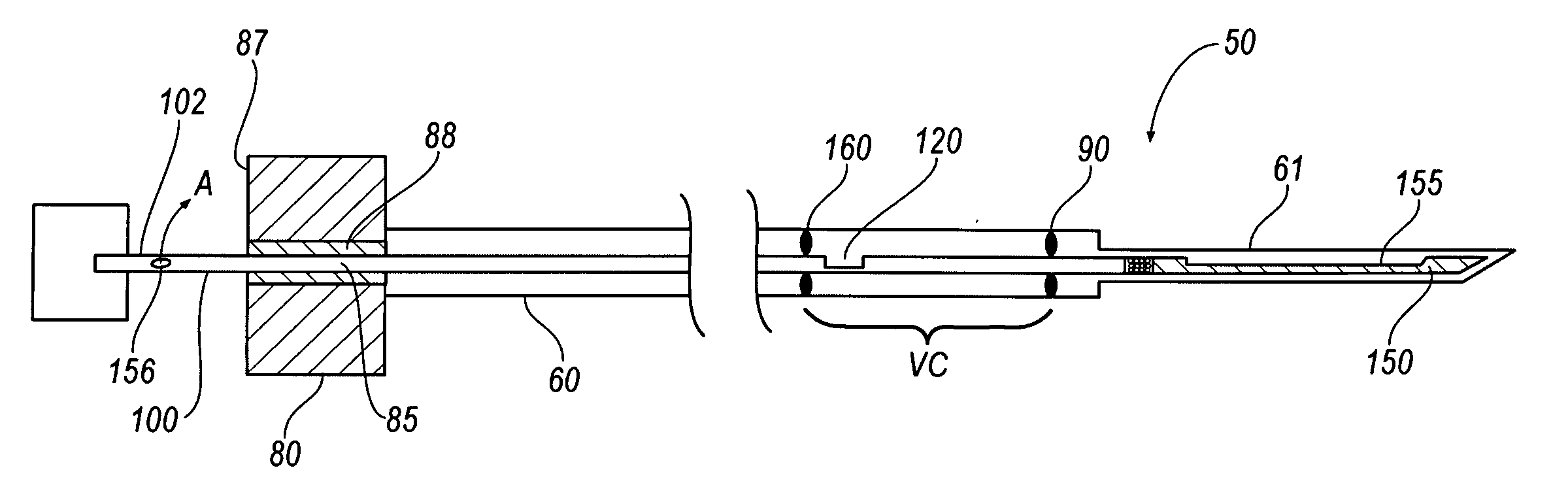
[0051]FIGS. 5-10 depict a needle set 50 for a biopsy device. Needle set 50 includes an inner member 100 slidably disposed within a lumen 58 of an outer member 60. Outer member 60 has a tip member 61 attached to a center portion 70 and a hub member 80 positioned on the proximal end of outer member 60. Tip member 61 has a working end 63 with an opening 63(a) therethrough, an opposite end 64 and a tip lumen 65 defined therebetween. As seen most clearly in FIG. 6, center portion 70 has a first end 71 hermetically connected to the opposite end 64 of the tip member 61 and a second end 73. A center lumen 75 is defined between first and second ends 71 and 73. The center lumen 75 is in fluid communication with the tip lumen 65. Hub member 80 is positioned on the second end 73 of the center portion 70. Hub member 80 defines a hub lumen 85 that is in fluid communication with the center lumen 75. The hub lumen 85 is also in fluid communication with a pair of openings 86a, 87a defined in opposit...

embodiment 200

[0089]FIGS. 30A-30D illustrate another embodiment 200″ of a biopsy device having a cutting element mounted to a housing. With reference to FIG. 30A, the biopsy device 200″ includes a housing 400 having a cutting element 402. The cutting element 402 includes an inner cannula 404 and an outer cannula 406. As best illustrated in FIG. 30B, the inner cannula 404 has a sharpened tip 405 formed at its distal end 414. A tissue receiving aperture 412 is formed proximal to the sharpened tip 405 and is configured for receiving tissue to be excised in the cutting process to be described below.

[0090] Still referring to FIG. 30B, the inner cannula 404 is slidably disposed within the outer cannula 406. Preferably, the outer cannula 406 includes a razor sharpened beveled edge 416 formed at its distal end 418 for enhancing its ability to cut tissue.

[0091] A vacuum chamber 408 is disposed proximate the proximal end 420 of the inner cannula 404. The vacuum chamber 408 operates to cause a vacuum to be...


PUM


Abstract

A biopsy device having a cutting element is disclosed. The cutting element includes an inner cannula having a tissue receiving aperture disposed proximate a distal end thereof and an inner lumen. The inner cannula is slidably disposed within the inner lumen of an outer cannula. A vacuum chamber is disposed about at least a portion of the cutting element and is configured to create a vacuum in the cutting element during a biopsy procedure. The inner cannula is advanced distally outwardly and to cause the vacuum to be generated in the vacuum chamber. The vacuum is delivered to the cutting element whereby tissue is drawn into the tissue receiving aperture. The outer cannula is advanced distally outwardly after the inner cannula such that tissue drawn into the tissue cutting aperture is severed.

Description

CROSS REFERENCE TO RELATED APPLICATION [0001] This application is a Continuation-in-Part of U.S. Pat. application Ser. No. 10 / 964,959 filed Oct. 14, 2004 which claims priority to U.S. provisional patent application Ser. No. 60 / 510,866 filed on Oct. 14, 2003, which both applications are incorporated herein by reference in their entireties.FIELD OF THE INVENTION [0002] The present invention generally relates to the field of tissue sampling and harvesting. More specifically, the invention relates to biopsy needle sets and devices. BACKGROUND OF THE INVENTION [0003] In the practice of diagnostic medicine, it is often necessary or desirable to perform a biopsy, or to sample selected tissue from a living patient for medical evaluation. Cytological and histological studies of the biopsy sample can then be performed as an aid to the diagnosis and treatment of disease. Biopsies can be useful in diagnosing and treating various forms of cancer, as well as other diseases in which a localized ar...

Claims


Application Information

Patent Timeline
Patent Type & Authority Applications(United States)
IPC IPC(8): A61B10/00A61B17/32A61B10/02
CPCA61B10/0275A61B10/0283A61B2010/0208A61B10/0266A61B10/02
Inventor MARK, JOSEPH L.MILLER, MICHAEL E.HOFFA, MICHAELNICOSON, ZACHARY R.HARDIN, TERRY D.JARIAL, INDERJEET S.HODGE, WILLIAM O.
Owner PROMEX TECH
Why Eureka
Try Eureka