
Breast compression assembly for use in MRI biopsy procedure

a compression assembly and breast technology, applied in the field of breast compression assembly for use in mri biopsy procedure, can solve the problems of limiting the number of such apertures, the corresponding number of access points available to the clinician, and the less effective the compression member will be in securing the breast, and the limitation of the number of locations

Inactive Publication Date: 2010-11-25
DEVICOR MEDICAL PROD
View PDF7 Cites 10 Cited by
  • Summary
  • Abstract
  • Description
  • Claims
  • Application Information

AI Technical Summary

Benefits of technology

The present invention is a compression assembly for use during medical procedures such as MRI and biopsy. The assembly includes a frame that can be attached to a localization fixture. The frame has compression members that can be adjusted or removed to provide access to the patient's breast at a desired location. The technical effect of this invention is to provide a flexible and adjustable compression assembly that allows physicians to easily access the patient's breast during medical procedures.

Problems solved by technology

The number of such apertures, and the corresponding number of access points available to the clinician, is limited in order to provide enough surface area to sufficiently restrain the breast during the procedure.
Generally, the greater the number of access points present in a compression member, the less effective the compression member will be in securing the breast during the procedure.
Providing fixed openings through which a biopsy device may be inserted may limit the number of locations through which a clinician may gain access once the compression members are in place.
Rather than reposition the compression members, clinicians may try to work within the limited access areas, thereby potentially decreasing the accuracy or efficacy of the biopsy procedure.
Additionally, fixed openings may provide less support than needed in open areas and closed areas may create too high a pressure on narrow areas of the breast.

Method used


Image

  • Breast compression assembly for use in MRI biopsy procedure
  • Breast compression assembly for use in MRI biopsy procedure
  • Breast compression assembly for use in MRI biopsy procedure

Examples


Embodiment Construction

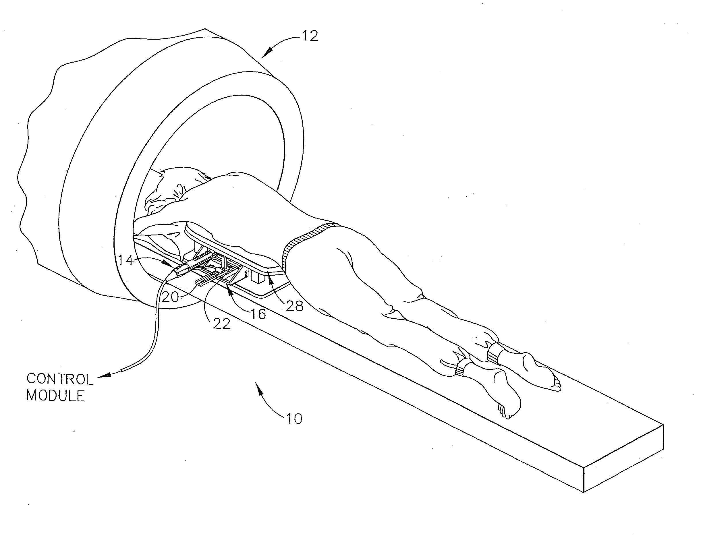
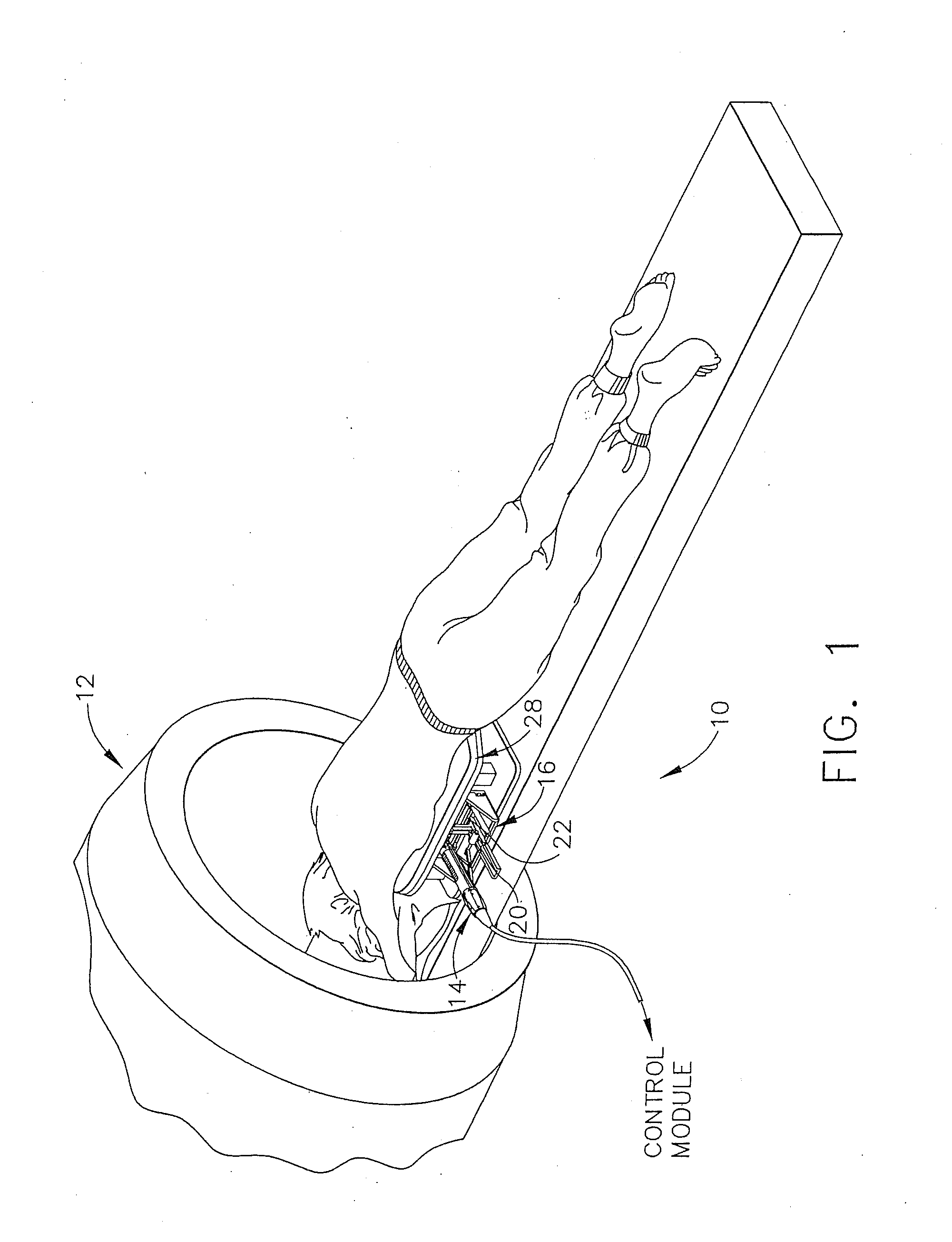
[0042]Turning to the Drawings, wherein like numerals denote like components throughout the several views, in FIG. 1, a Magnetic Resonance Imaging (MRI) biopsy system 10, hereinafter biopsy system 10, includes an MRI machine 12, a patient support 28, a localization fixture 16, and a biopsy device 14.

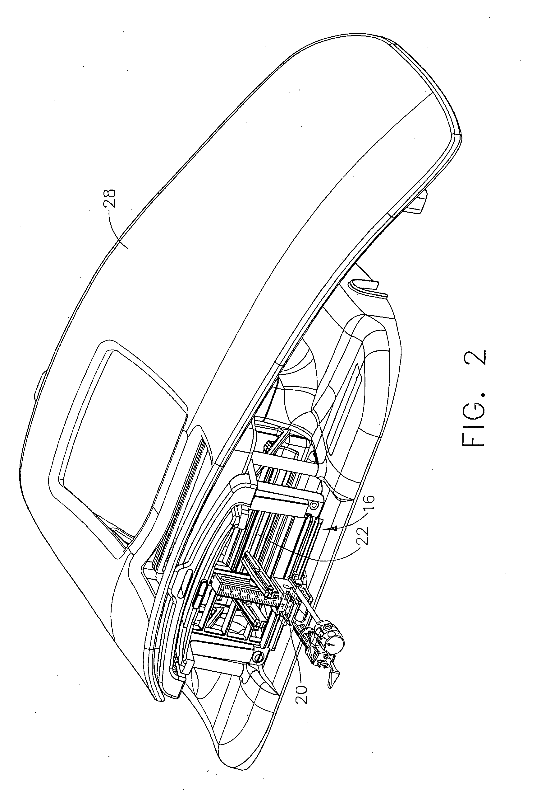
[0043]Referring to FIGS. 1-3, the biopsy system 10 includes a control module (not shown) that typically is placed outside of a shielded room containing an MRI machine 12, or at least spaced away, to mitigate detrimental interaction with its strong magnetic field and / or sensitive radio frequency (RF) signal detection antennas. The control module controls and powers the biopsy device 14, which is compatible for use in close proximity to the MRI machine 12. An example of a biopsy device 14 is the afore-mentioned MAMMOTOME™ instrument. The biopsy device 14 is accurately positioned by a localization fixture 16 that is attached to a patient support 28, which supports a patient throughout the du...


PUM


Abstract

A compression assembly is operable to localize a patient's breast. The compression assembly comprises a frame and a plurality of slats. The frame defines a plurality of tracks. The frame is configured to engage a breast localization fixture. The slats are coupled with the frame. Portions of the slats are disposed in the tracks. One or more of the slats are movable relative to the frame to provide adjustable access to a patient's breast engaged by the compression assembly. The slats may be slid and / or rotated relative to the frame. In some versions, the tracks and slats are provided in two sets. Each set lies along a respective plane, with the two planes being parallel to each other. The slats of one set may ratchetingly engage the slats of the other set to restrain slat movement. In some versions, the slats are removable from the frame for increased access.

Description

PRIORITY[0001]This application is a divisional of U.S. patent application Ser. No. 11 / 395,796, entitled “MRI Biopsy Device,” filed Mar. 31, 2006, published as U.S. Pub. No. 2007 / 0232953 on Oct. 4, 2007, the disclosure of which is incorporated by reference herein.FIELD OF THE INVENTION[0002]The present invention relates, in general, to a method of imaging assisted tissue sampling and, more particularly, to an improved method for positioning a biopsy probe with respect to a magnetic resonance imaging (MRI) breast coil for acquiring subcutaneous biopsies and for removing lesions.BACKGROUND OF THE INVENTION[0003]Recently, core biopsy devices have been combined with imaging technology to better target a lesion in breast tissue. One such commercially available product is marketed under the trademark name MAMMOTOME™, by Ethicon Endo-Surgery, Inc. An embodiment of such a device is described in U.S. Pat. No. 5,526,822 issued to Burbank, et al., on Jun. 18, 1996, and is herein incorporated by...

Claims


Application Information

Patent Timeline
Patent Type & Authority Applications(United States)
IPC IPC(8): A61B5/055
CPCA61B10/0041A61B2019/205A61B19/203A61B90/17A61B90/14
Inventor DIETZ, TIMOTHY G.CLEM, WILLIAM E.
Owner DEVICOR MEDICAL PROD
Learn More