Means and method for marking human tissue that may be malignant

a human tissue and malignant technology, applied in the field of human tissue marking methods and devices, can solve the problems of compromising future successful localization, increasing the frequency of diagnostic imaging for small lesions throughout the body, and all devices have the significant limitation of requiring image guided localization procedures, so as to achieve accurate placement of permanent magnets.

Inactive Publication Date: 2008-02-14
FISCHELL ROBERT E +1
View PDF9 Cites 8 Cited by
  • Summary
  • Abstract
  • Description
  • Claims
  • Application Information

AI Technical Summary

Benefits of technology

[0016] It is also envisioned to first place the tip of the insertion needle (which is also the distal tip of the magnet) at the center of the suspected tissue volume. The next step would use a spring release to quickly advance the tip of the needle by half the length of the magnet and then use a second spring release to pull back the needle so that the magnet would lie centered in the suspected tissue. It is believed that this technique could more accurately place the permanent magnet at the center of the suspected tissue volume.
[0017] Described herein are a means and method for placing a permanent magnet within the suspected tissue volume by placing it through the inner lumen of a large core needle biopsy device, which has been first used to take a sample of breast tissue. A flexible, magnet insertion cannula containing an elongated magnet marker with an anchoring mechanism compressed inside of the cannula is positioned through the inner lumen of the biopsy device which has just been used to take a sample of a suspected tissue volume. The magnet marker is positioned by using a plunger to push the magnet out of the magnet insertion cannula through an opening at the end of the magnet insertion cannula. Upon exiting the magnet insertion cannula, the compressed anchoring mechan

Problems solved by technology

In addition, the implantation of a small metal “clip” marker following large core biopsy under image guidance may be used when the visualized target has been substantially removed during the diagnostic procedure (thus compromising future successful localization).
The explosive growth of diagnostic imaging has increased the frequency of detection of small lesions throughout the body that cannot be seen or felt by the surgeon who is charged with the task of removing the suspected tissue volume.
These devices all have the significant limitation of requiring the image guided localization procedure immediately before the surgery.
The need for immediate preoperative localization frequently creates logistical problems for radiology departments and operating room personnel.
The need for immediate preoperative localization not only creates logistical problems for rad

Method used


Image

  • Means and method for marking human tissue that may be malignant
  • Means and method for marking human tissue that may be malignant
  • Means and method for marking human tissue that may be malignant

Examples


Embodiment Construction

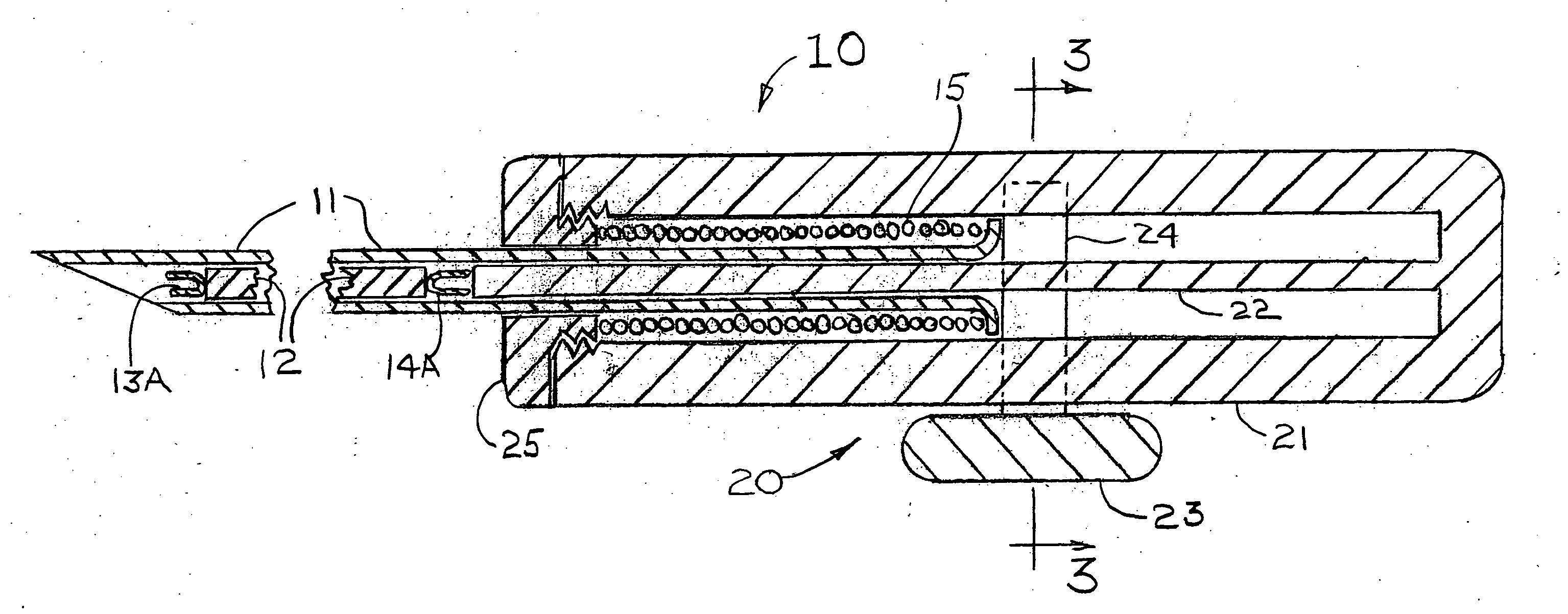
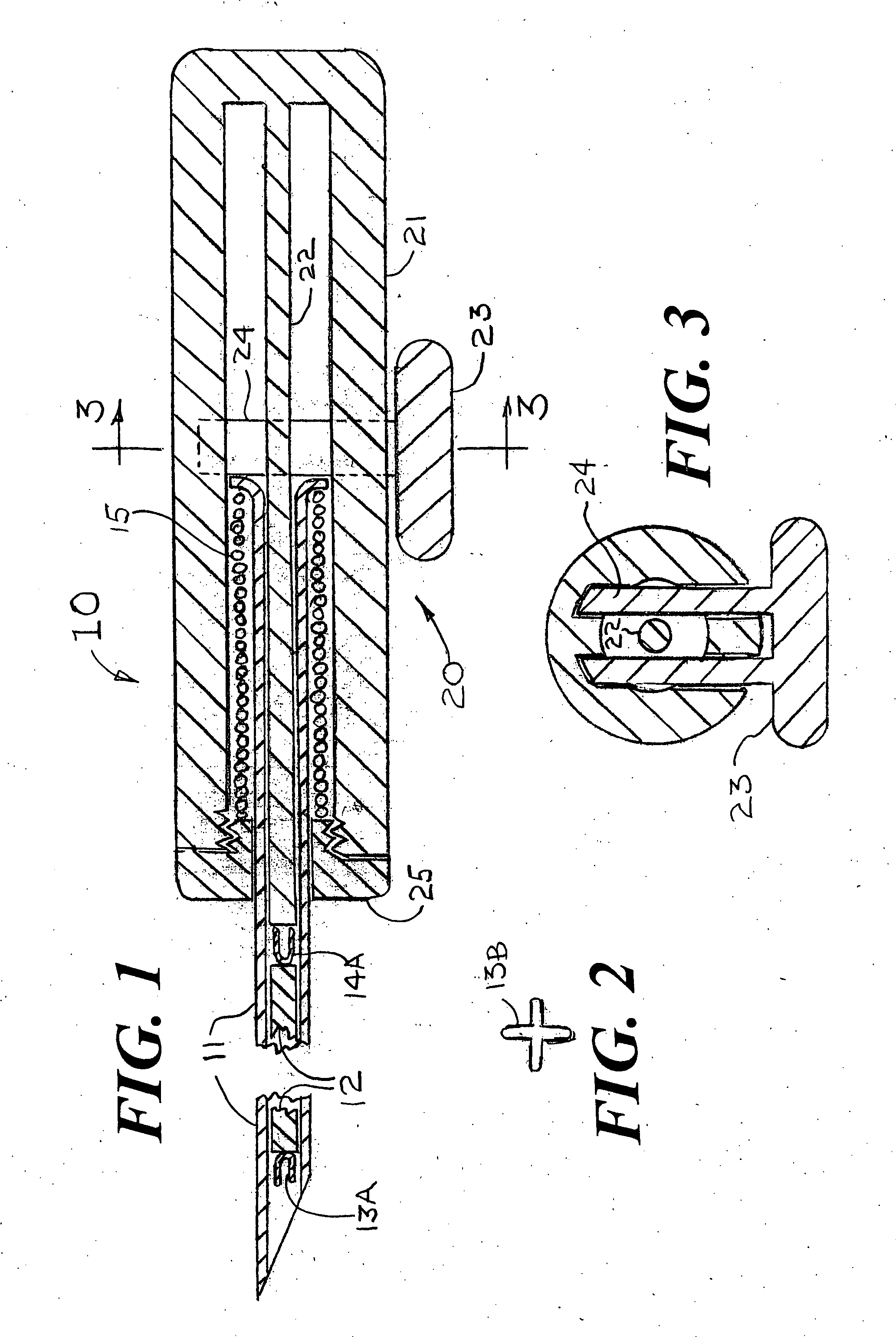
[0043]FIG. 1 shows a magnet injector 10 having a cannula 11 into which is placed a permanent magnet 12 having a pre-deployed distal anchor 13A fixedly attached at the magnet's distal end and a pre-deployed proximal anchor 14A fixedly attached at the magnet's proximal end. As shown in FIGS. 10A, 10B, 11A, 11B, 12 and 13, it is also conceived that the magnet could have one or more anchors deployed near the center of the magnet that also would be used to stabilize the position of the magnet within the breast. The shape of the deployed distal anchor 13B is shown in FIG. 2. The cannula 11 is positioned within a handle 20 that has an outer cylinder 21, an inner cylinder 22 and a spring release handle 23 that is attached to a spring holder 24 that keeps the spring 15 from expanding until the magnet 12 is ready for release within the suspected tissue volume. The cross section at 3-3 of FIG. 1 is shown as FIG. 3 that provides additional details of the spring release handle 23, the spring hol...


PUM


Abstract

Disclosed herein is a system for placing an elongated permanent magnet into a volume of tissue within a human body, including placement following a large core needle tissue biopsy procedure, where the tissue is suspected of being cancerous. The magnet's position is then detected by a magnet locating system that is used by a surgeon to find and remove the suspected tissue volume including a margin of tissue to assure that any and all cancer cells have been excised.

Description

REFERENCE TO A PRIOR PATENT APPLICATION [0001] This is a continuation-in-part application of the U.S. patent application Ser. No. 11 / 502,906 filed on Aug. 14, 2006.FIELD OF USE [0002] This invention is in the field of methods and devices for marking human tissue that may be cancerous so that tissue can be excised by a surgeon. BACKGROUND OF THE INVENTION [0003] The need for accurate preoperative image guided localization of nonpalpable breast lesions has been well described, and the frequency of use for this technique is increasing. Not only mammographically detected lesions require localization, but also lesions that may be found by any other imaging technique such as ultrasound, MRI, nuclear medicine or other technologies not yet described. Such localizations generally require the positioning of a temporary marker, most frequently constructed of a metal anchor on the end of a wire inserted through a needle that has been accurately positioned by image guidance prior to the release ...

Claims


Application Information

Patent Timeline
IPC IPC(8): A61M37/00
CPCA61M37/0069
Inventor FISCHELL, ROBERT E.MULLEN, DAVID J.
Owner FISCHELL ROBERT E
Why Eureka
Try Eureka