
Heating cooker

a technology for heating cookers and cookers, which is applied in the field of heating cookers, can solve the problems of difficulty in making hot air that blows out there, and uneven cooking of the articles to be heated, so as to achieve the effect of reducing the uneven temperature inside the heating chamber

Inactive Publication Date: 2007-05-17
SHARP KK
View PDF32 Cites 15 Cited by
  • Summary
  • Abstract
  • Description
  • Claims
  • Application Information

AI Technical Summary

Benefits of technology

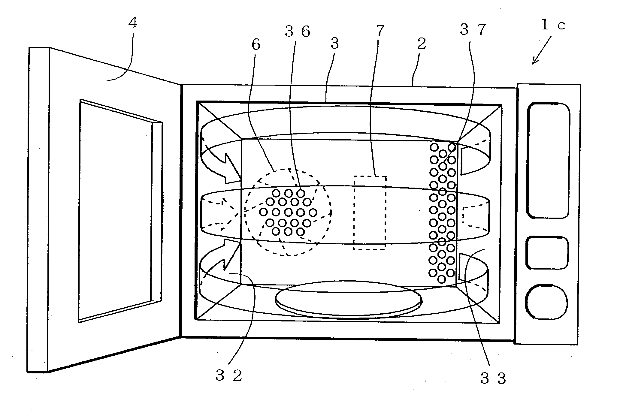
[0009] Specifically, according to a first invention, a heating cooker is characterized in that a hot air blown out through a blowoff port is made to flow continuously along at least three inner walls constituting a heating chamber. This makes it possible to make the hot air spread to every corner of the heating chamber, and thus helps minimize unevenness in the temperature inside the heating chamber.
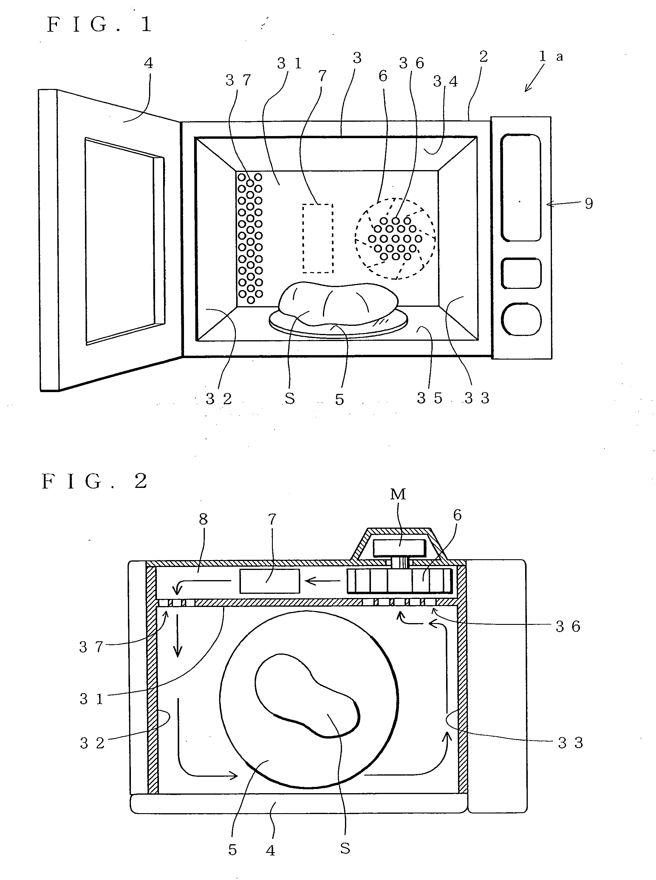
[0012] Moreover, according to a second invention, a heating cooker is characterized in that mutually opposite two inner walls, which constitute a heating chamber, each have a blowoff port and a suction port in such a way that the blowoff port formed in each of the two inner walls faces the suction port formed in the other of the two inner walls. With this structure, the hot air introduced through one blowoff port into the heating chamber flows in a substantially linear manner, and is then sucked via the opposite suction port thereof. Then, the hot air is introduced through another blowoff port into the heating chamber, then again flows in a substantially linear manner, and is then sucked via the opposite suction port thereof. This makes the hot air circulate completely throughout the heating chamber. This makes it possible to apply heat uniformly to an article to be heated especially in the depth direction.
[0013] Moreover, according to a third invention, a heating cooker is characterized in that a blowoff port is formed in a side wall of a heating chamber, and a suction port is formed in at least one or both of a ceiling and a bottom wall thereof. With this structure, the hot air introduced through the blowoff port into the heating chamber flows upward or downward in a spiral manner along the side wall of the heating chamber, and is then sucked via the suction port. This also makes it possible to make the hot air spread to every comer of the heating chamber, and thus helps minimize unevenness in the temperature inside the heating chamber.

Problems solved by technology

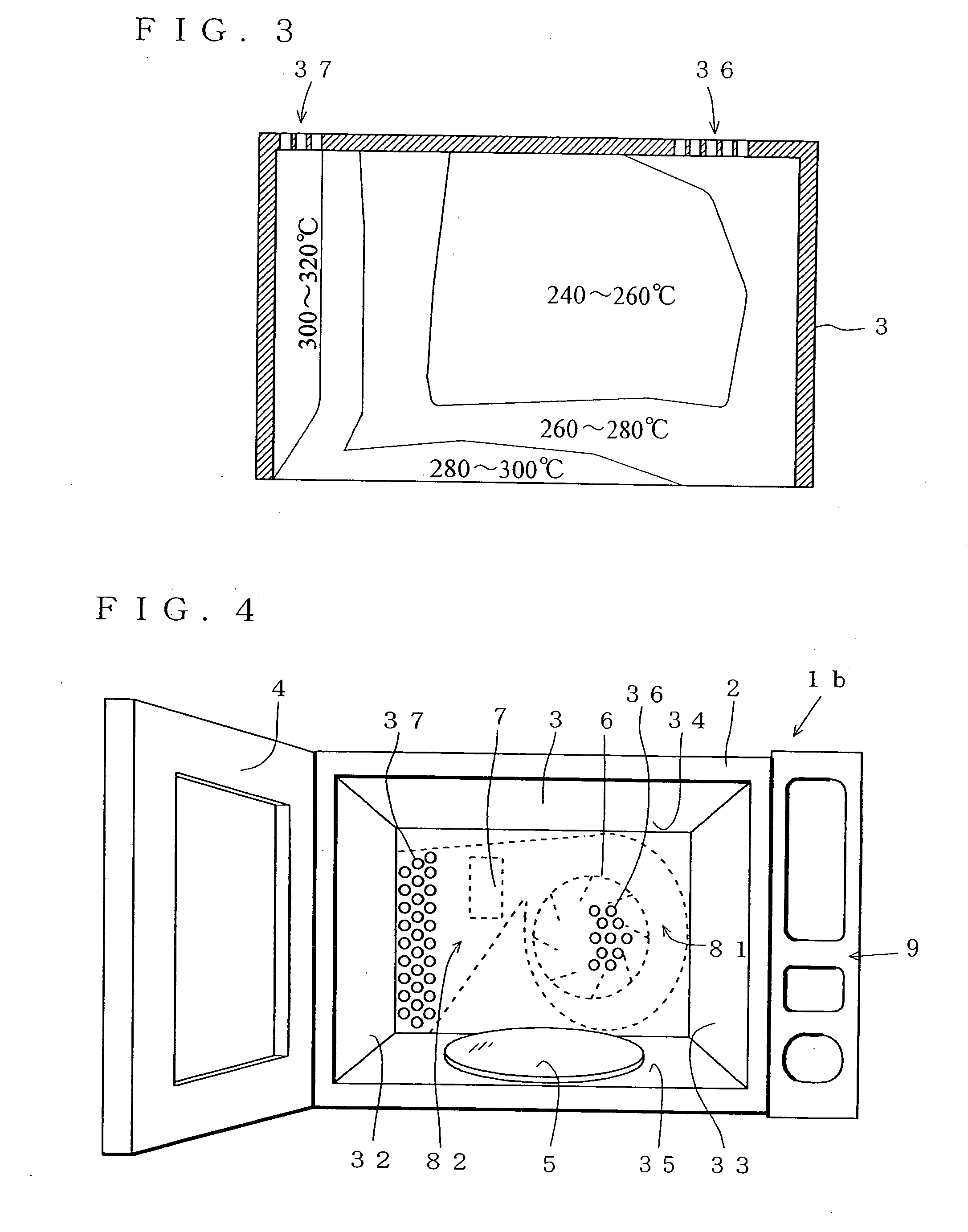
This makes it difficult to make the hot air that blows out therefrom reach a position away from the blowoff port 37 and the suction port 36.
The problem here is that such unevenness in the temperature inside the heating chamber 3 results in uneven cooking of the article to be heated S depending on where it is placed in the heating chamber 3.
However, in that case, the following problems arise.
Moreover, such a flow of air to the suction port 36 that occurs at the center of the heating chamber 3 in a concentrated manner results in uneven cooking of the article to be heated S depending on where it is placed in the heating chamber 3 due to the influence of the flow of the hot air.

Method used


Image

  • Heating cooker
  • Heating cooker
  • Heating cooker

Examples


Embodiment Construction

[0042] Hereinafter, a heating cooker of the present invention will be described with reference to the drawings. It is to be understood, however, that the present invention is not limited to any of the examples specifically described below.

[0043] A front perspective view showing one embodiment of the heating cooker of a first invention is shown in FIG. 1, and a plan sectional view thereof is shown in FIG. 2. This heating cooker 1a has a cabinet 2 that is insulated with insulating means and that has an opening at the front face thereof, a heating chamber 3 that is formed inside the cabinet 2 to permit an article to be cooked to be placed therein, a door 4 that openably closes the opening, and an operation portion 9 that receives / displays cooking conditions.

[0044] The heating chamber 3 has, in the bottom wall thereof, a hole (not shown), through which a rotation axis (not shown) is projected. On top thereof, a turntable 5 is provided for mounting an article to be heated S thereon. Mo...


PUM


Abstract

A heating cooker has an air-sucking opening (36) at one side of opposed edge portions of an inner wall (31) and an air-blowing opening (37) at the other side. Heated air sent into a heating room (3) from the blowing opening (37) flows along three inner walls (32, 4 (door), 33) and sucked from the sucking opening (36). This structure enables the heated air to pervade the entire heating room (3). As a result, temperature variations in the heating room (3) are suppressed to a low level and an object to be heated is evenly baked.

Description

TECHNICAL FIELD [0001] The present invention relates to a heating cooker, more particularly to a so-called hot air circulation heating cooker that makes a hot air circulate so as to cook an article to be heated. BACKGROUND ART [0002] Heating cookers such as convection ovens using hot air circulation to cook an article to be heated that is put in the heating chamber are provided with a blower (blowing means) for producing forced circulation of the air inside the heating chamber and a heater (heating means) for heating the circulated air, so as to speed up cooking time and make the temperature inside the chamber uniform, and thereby achieve improved heating performance. When the heating cooker is used, it is necessary to appropriately set the temperature inside the heating chamber, the cooking time, and the like. Some models of heating cookers have, as well as an oven cooking function, an electromagnetic wave heating function, a dielectric heating function, and a steam cooking functio...

Claims


Application Information

Patent Timeline
Patent Type & Authority Applications(United States)
IPC IPC(8): F24C15/32F27D11/00F24C1/00
CPCF24C15/325
Inventor SHIRAICHI, YUKISHIGEOHTSUKA, MASAKI
Owner SHARP KK
Learn More