System and method for deflection compensation in power drive system for connection of tubulars

Inactive Publication Date: 2007-05-17
WEATHERFORD TECH HLDG LLC
View PDF30 Cites 42 Cited by
  • Summary
  • Abstract
  • Description
  • Claims
  • Application Information

AI Technical Summary

Benefits of technology

[0017] In another embodiment, a system for connecting threaded tubular members for use in a wellbore or a riser system is provided. The system includes a power drive unit operable to rotate a first threaded tubular member relative to a second threaded tubular member; a power drive control system operably connected to the power drive unit, and including: a torque detector; a turns detector; and a computer receiving torque measurements taken by the torque detector and rotation measurements taken b

Problems solved by technology

For some oil well tubing, such API type connections are not sufficiently secure or leakproof.
In particular, as the petroleum industry has drilled deeper into the earth during exploration and production, increasing pressures have been encountered.
However, in addition to being highly subjective, such an approach fails to

Method used


Image

  • System and method for deflection compensation in power drive system for connection of tubulars
  • System and method for deflection compensation in power drive system for connection of tubulars
  • System and method for deflection compensation in power drive system for connection of tubulars

Examples


Embodiment Construction

[0036] The present invention generally provides methods and apparatus for characterizing pipe connections. In particular, an aspect of the present invention provides for characterizing the make-up of premium grade tubing.

[0037] As used herein, premium grade tubing refers to tubing wherein one length can be connected to another by means of a connection incorporating a shoulder which assists in sealing of the connection by way of a metal-to-metal contact.

Premium Grade Tubing

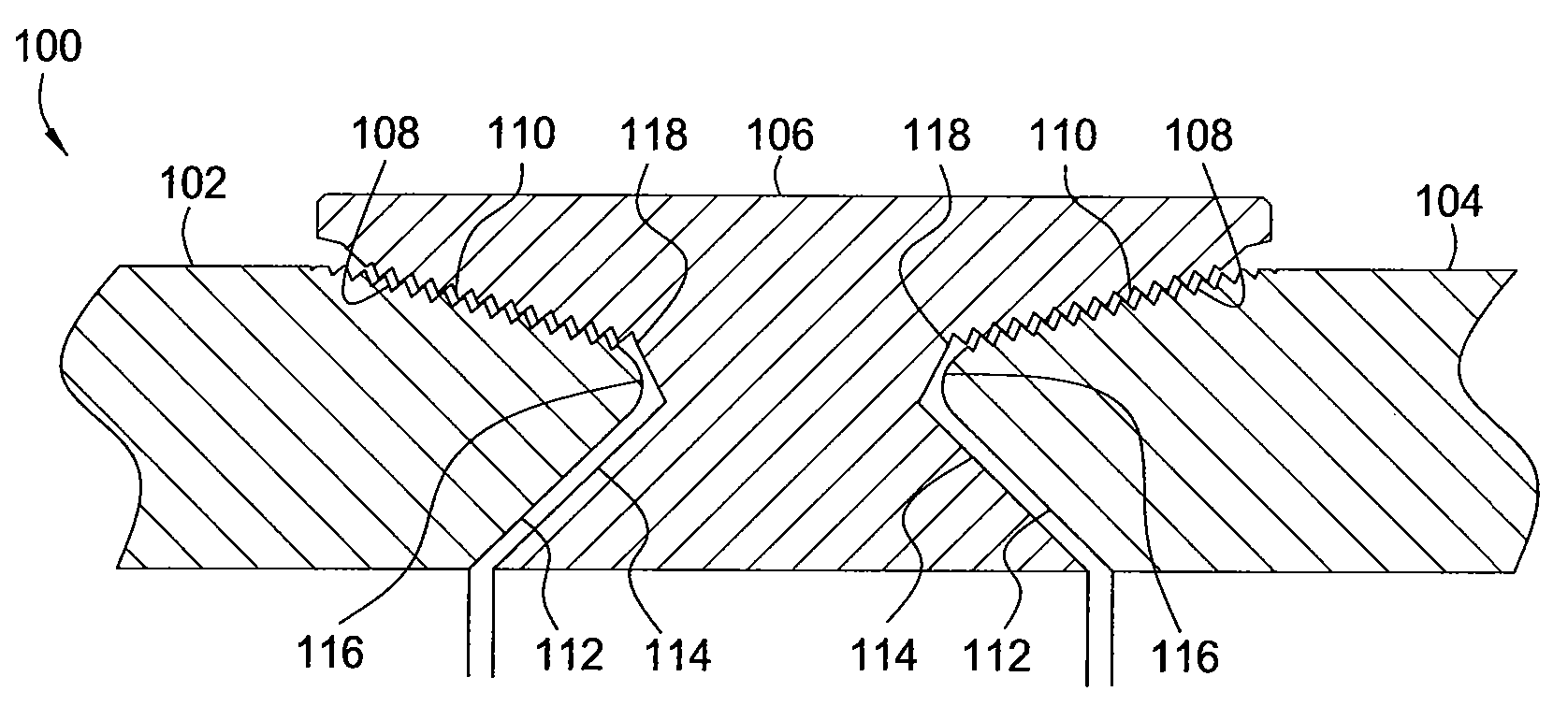
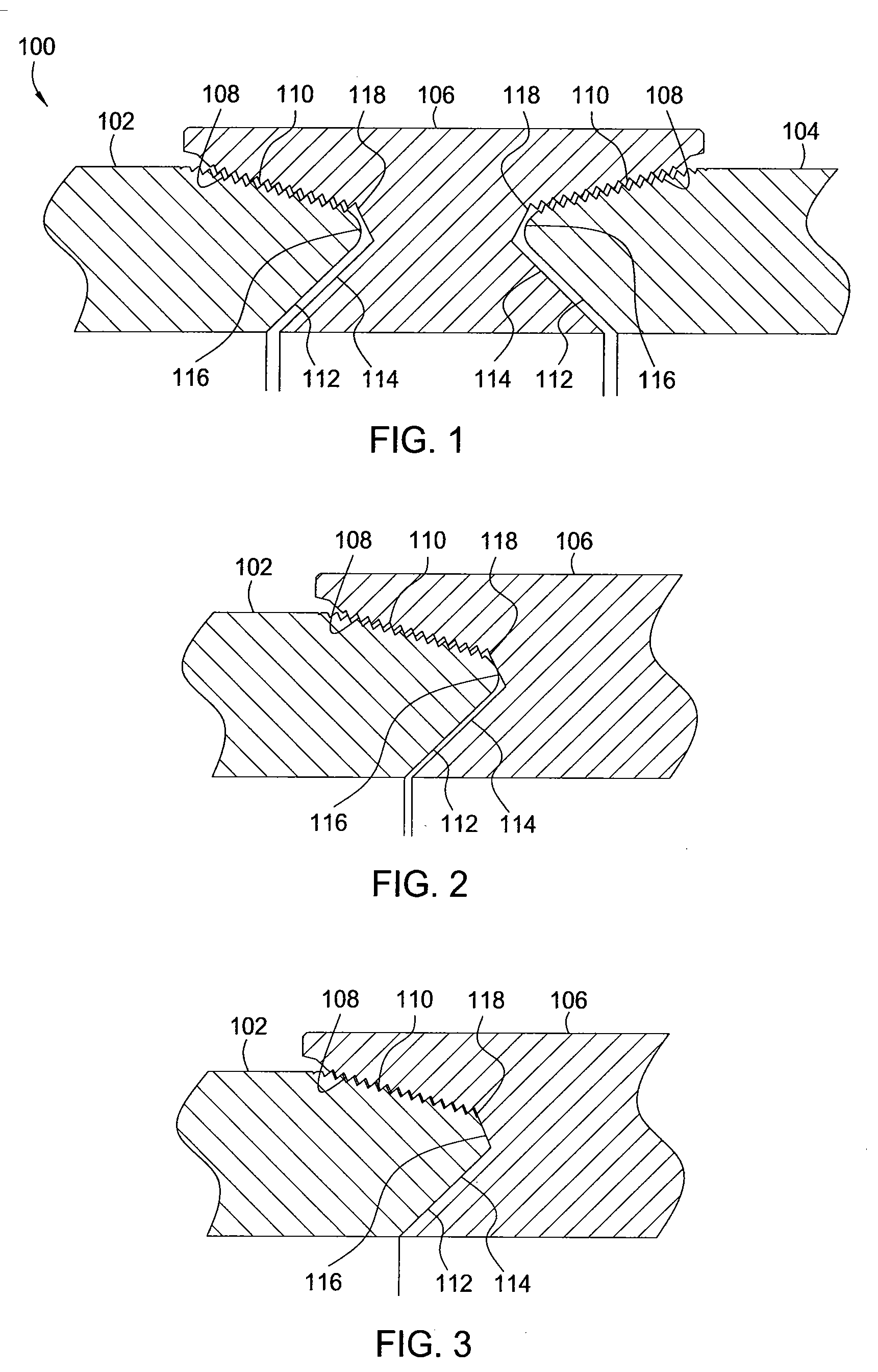
[0038]FIG. 1 illustrates one form of a premium grade tubing connection to which aspects of the present invention are applicable. In particular, FIG. 1 shows a tapered premium grade tubing assembly 100 having a first tubing length 102 joined to a second tubing length 104 through a tubing coupling or box 106. The end of each tubing length 102 and 104 has a tapered externally-threaded surface 108 which co-operates with a correspondingly tapered internally-threaded surface 110 on the coupling 106. Each tubing lengt...


PUM

PropertyMeasurementUnit
Torqueaaaaaaaaaa

Abstract

The present invention generally provides methods and apparatus for connecting threaded members while ensuring that a proper connection is made, particularly for premium grade connections. In one embodiment, a method of connecting threaded tubular members for use in a wellbore or a riser system is provided. The method includes the acts of operating a power drive unit, thereby rotating a first threaded tubular member relative to a second threaded tubular member; measuring the rotation of the first threaded tubular member; and compensating the rotation measurement by subtracting a deflection of at least one of: the power drive unit, and one of the tubular members.

Description

CROSS-REFERENCE TO RELATED APPLICATIONS [0001] This application claims benefit of U.S. provisional Patent Application Ser. No. 60 / 763,306, filed Jan. 30, 2006, which is herein incorporated by reference in its entirety. [0002] This application is a continuation-in-part of co-pending U.S. patent application Ser. No. 10 / 723,290 (Atty. Docket No. WEAT / 0310), filed Nov. 25, 2003, which claims benefit of U.S. provisional Patent Application Ser. No. 60 / 429,681, filed Nov. 27, 2002. U.S. patent application Ser. No. 10 / 723,290 is a continuation-in-part of U.S. patent application Ser. No. 09 / 860,127 (Atty. Docket No. WEAT / 0116), filed May 17, 2001, now U.S. Pat. No. 6,742,596. U.S. patent application Ser. No. 10 / 723,290 is also a continuation-in-part of U.S. patent application Ser. No. 10 / 389,483, filed Mar. 14, 2003 (Atty. Docket No. WEAT / 0146.C1). These applications are herein incorporated by reference in their entireties.BACKGROUND OF THE INVENTION [0003] 1. Field of the Invention [0004] E...

Claims


Application Information

Patent Timeline
IPC IPC(8): E21B19/18E21B47/00
CPCE21B19/165Y10T29/49767E21B47/0006E21B19/166E21B47/007
Inventor BOUTWELL, DOYLENEWMAN, JOHNRUARK, GRAHAMDAUPHINE, AARON
Owner WEATHERFORD TECH HLDG LLC
Why Eureka
Try Eureka