Torsional vibration damper for a hydrodynamic clutch arrangement

a technology of torsional vibration and hydrodynamic clutch, which is applied in the direction of fluid couplings, gearings, couplings, etc., can solve the problems of preventing the realization of direct connection and the solution is not very versatile in application, and achieves the effect of convenient installation

Inactive Publication Date: 2007-05-17
ZF FRIEDRICHSHAFEN AG
View PDF4 Cites 17 Cited by
  • Summary
  • Abstract
  • Description
  • Claims
  • Application Information

AI Technical Summary

Benefits of technology

[0005] It is an object of the present invention to connect a torsional vibration damper to a hydrodynamic clutch arrangement in such a way that the housing of the hydrodynamic clutch arrangement can be easily installed on a drive and that the degree to which the wobbling movements generated by the drive are transmitted to the housing can be at least reduced, regardless of whether the torsional vibration damper is present or not.
[0009] The takeoff-side damping element preferably has not only at least one cover plate, which serves to actuate the elastic elements of the torsional vibration damper, but also a takeoff hub, connected nonrotatably to this cover plate, which hub forms an axially and radially secured receptacle for the drive side of the flexplate, which is especially advantageous if the takeoff hub is axially and / or radially supported against the drive. In an advantageous embodiment, the takeoff hub is therefore supported by way of a support ring either directly on the drive or by way of a component permanently attached to the drive such as the flywheel mass element. This support of the takeoff hub by means of the support ring is advantageously accomplished by way of a bearing arrangement, where, in the ideal case, both radial support and axial support are provided. As a result, wear between the drive or the flywheel mass element, which defines the movements of the drive-side damping element of the torsional vibration damper, and the support ring, which copies the movements of the takeoff-side damping element of the torsional vibration damper, is minimized. In an especially simple embodiment of the bearing arrangement, all the bearings can be designed as journal bearings. In an especially low-friction embodiment, all the bearings are realized in the form of roller bearings, where combinations of journal bearings and roller bearings are also conceivable.

Problems solved by technology

Because the fastening elements are no longer accessible after the hydrodynamic clutch arrangement has been installed, it is necessary to provide a way to detach the drive-side damping element from the elastic elements remaining attached to the hydrodynamic clutch arrangement and from the takeoff-side damping element.
Providing this separability, however, causes wear-related problems with the axial positioning of the hydrodynamic clutch arrangement, because the free end of the drive-side damping element facing away from the drive and possibly the free end of a bearing journal provided in the radially inside area of the housing of the hydrodynamic clutch arrangement act as axial support for the hydrodynamic clutch arrangement, and both axial supports are provided in positions of relative rotational movement of the components which enter into axial contact with each other.
Because of its location effectively between the drive and the torsional vibration damper, however, this flexplate prevents the realization of a direct connection between the hydrodynamic clutch arrangement and the drive in the event that the torsional vibration damper is omitted.
Thus, this solution is not very versatile with respect to applications in the automobile industry, where it is known that frequently changing requirements call for constant adaptation to specific demands.

Method used


Image

  • Torsional vibration damper for a hydrodynamic clutch arrangement
  • Torsional vibration damper for a hydrodynamic clutch arrangement
  • Torsional vibration damper for a hydrodynamic clutch arrangement

Examples


Embodiment Construction

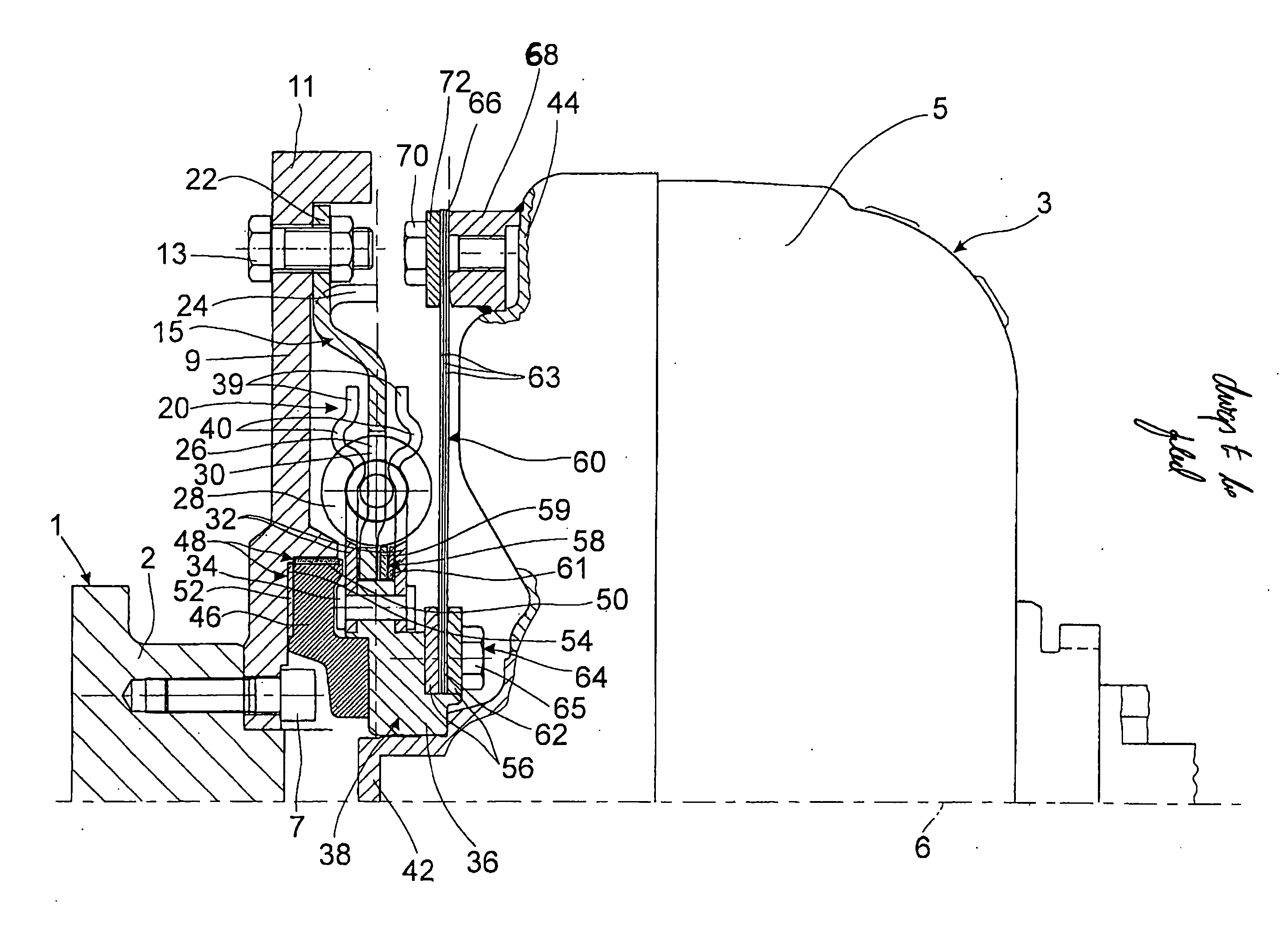
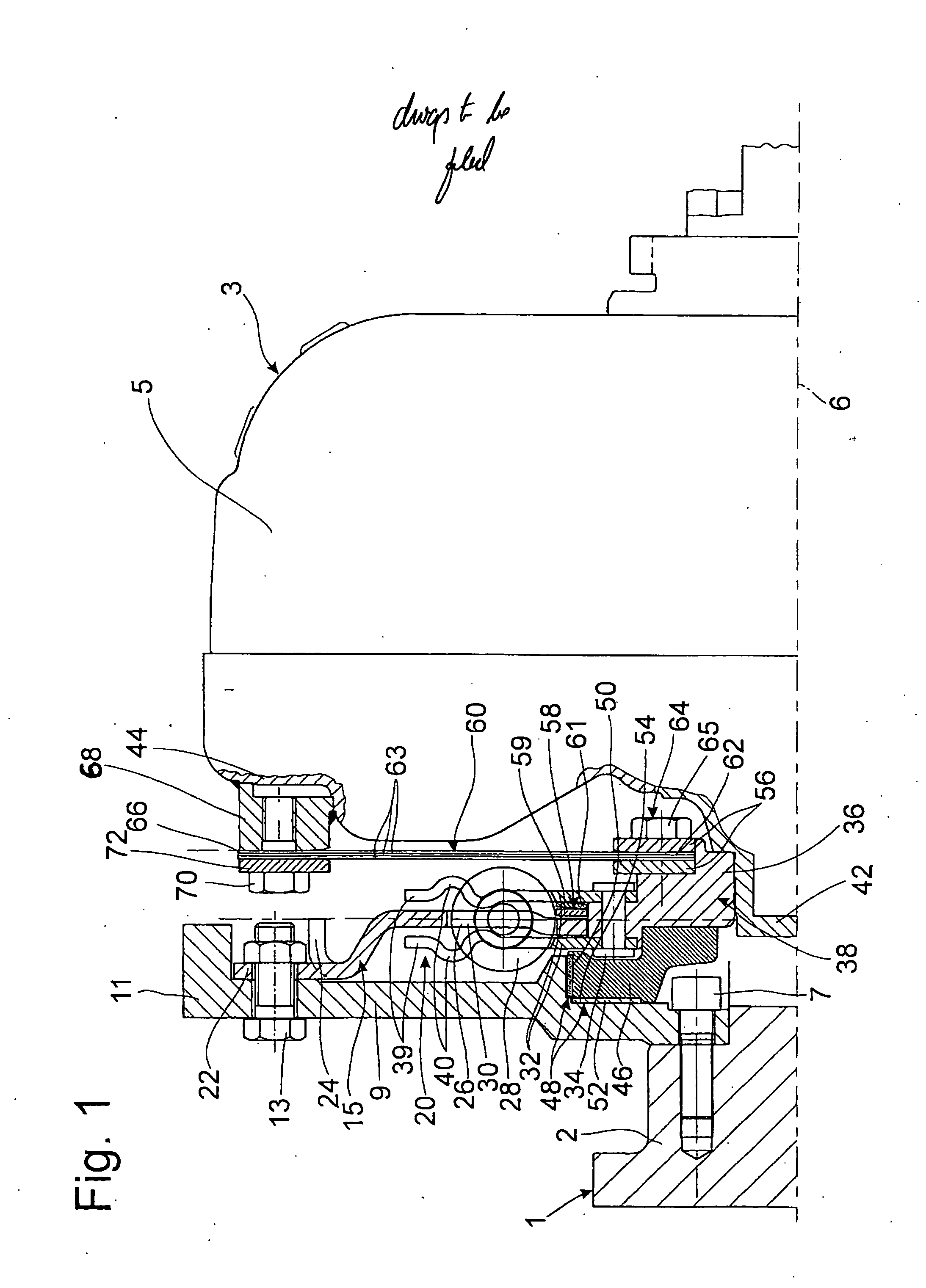
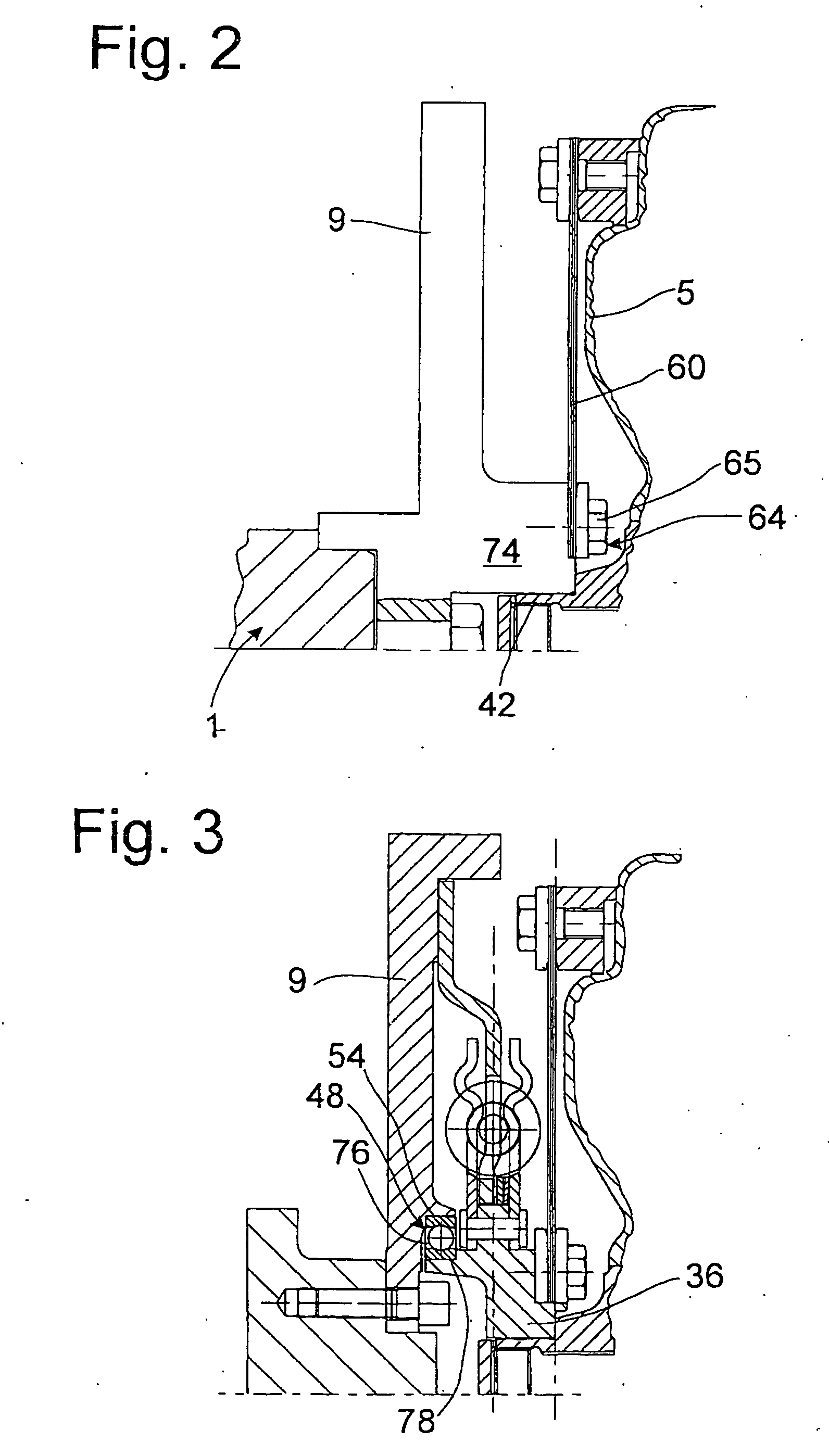
[0016]FIG. 1 shows a drive 1 in the form of a crankshaft 2 of an internal combustion engine (not shown) for a hydrodynamic clutch arrangement 3, realized as a torque converter or hydraulic clutch, for example, wherein the clutch arrangement 3 has a housing 5. The clutch arrangement 3 has essentially the same axis of rotation 6 as the drive 1.

[0017] A flywheel mass element 9 is attached to the crankshaft 2 by means of fastening elements 7. This flywheel mass element 9 extends outward essentially in the radial direction until its outer circumference merges with an axial extension 11 pointing toward the hydrodynamic clutch arrangement 3. Directly inside the axial extension 11 in the radial direction, a hub flange-shaped, drive-side damping element 15 of a torsional vibration damper 20 is attached to the flywheel mass element 9 by fastening elements 13. The fastening elements 13 are held in holding sections 22 of the damping element 15. These holding sections 22 are provided at predete...


PUM


Abstract

The torsional vibration damper acting between a drive and a housing of a hydrodynamic clutch arrangement includes a flywheel mass element, a drive-side damping element having a first side connected nonrotatably to the flywheel mass element, a takeoff-side damping element, the second side of the drive-side damping element being connected by elastic elements to the takeoff-side damping element for rotation in common, the elastic elements also allowing a small rotation of the drive-side damping element relative to the takeoff-side damping element, and an axially flexible drive plate. The takeoff-side damping element can be connected to the housing of the hydrodynamic clutch arrangement nonrotatably but with a certain freedom of axial movement by means of the drive plate.

Description

BACKGROUND OF THE INVENTION [0001] The invention pertains to a torsional vibration damper for a hydrodynamic clutch arrangement. [0002] A torsional vibration damper is, for example, known from U.S. Pat. No. 6,478,127. The torsional vibration damper is installed axially between a flywheel mass element, which is attached to a drive such as the crankshaft of an internal combustion engine, and a housing of the hydrodynamic clutch arrangement, which is realized as a torque converter. The torsional vibration damper is provided with a drive-side damping element, which is connected nonrotatably on one side to the flywheel mass element and connected for rotation in common on the other side by means of elastic elements to the takeoff-side damping element of the torsional vibration damper, the takeoff-side damping element being in functional connection by way of the hydrodynamic clutch arrangement with a takeoff formed by a gearbox input shaft. [0003] In the known torsional vibration damper, t...

Claims


Application Information

Patent Timeline
Patent Type & Authority Applications(United States)
IPC IPC(8): F16D33/00
CPCF16F15/1201F16H41/24
Inventor SCHMID, HERBERTJOHANN, HERBERTENDER, GEORG
Owner ZF FRIEDRICHSHAFEN AG
Why Eureka
Try Eureka