Technique for Shaping a Ribbon-Shaped Ion Beam

Active Publication Date: 2007-05-17
VARIAN SEMICON EQUIP ASSOC INC
View PDF10 Cites 19 Cited by
  • Summary
  • Abstract
  • Description
  • Claims
  • Application Information

AI Technical Summary

Benefits of technology

[0011] A technique for shaping a ribbon-shaped ion beam is disclosed. In one particular exemplary embodiment, the technique may be realized as an apparatus for shaping a ribbon-shaped ion beam. The apparatus may comprise an electrostatic lens having a substantiall

Problems solved by technology

However, this approach can only achieve a li

Method used


Image

  • Technique for Shaping a Ribbon-Shaped Ion Beam
  • Technique for Shaping a Ribbon-Shaped Ion Beam
  • Technique for Shaping a Ribbon-Shaped Ion Beam

Examples


Embodiment Construction

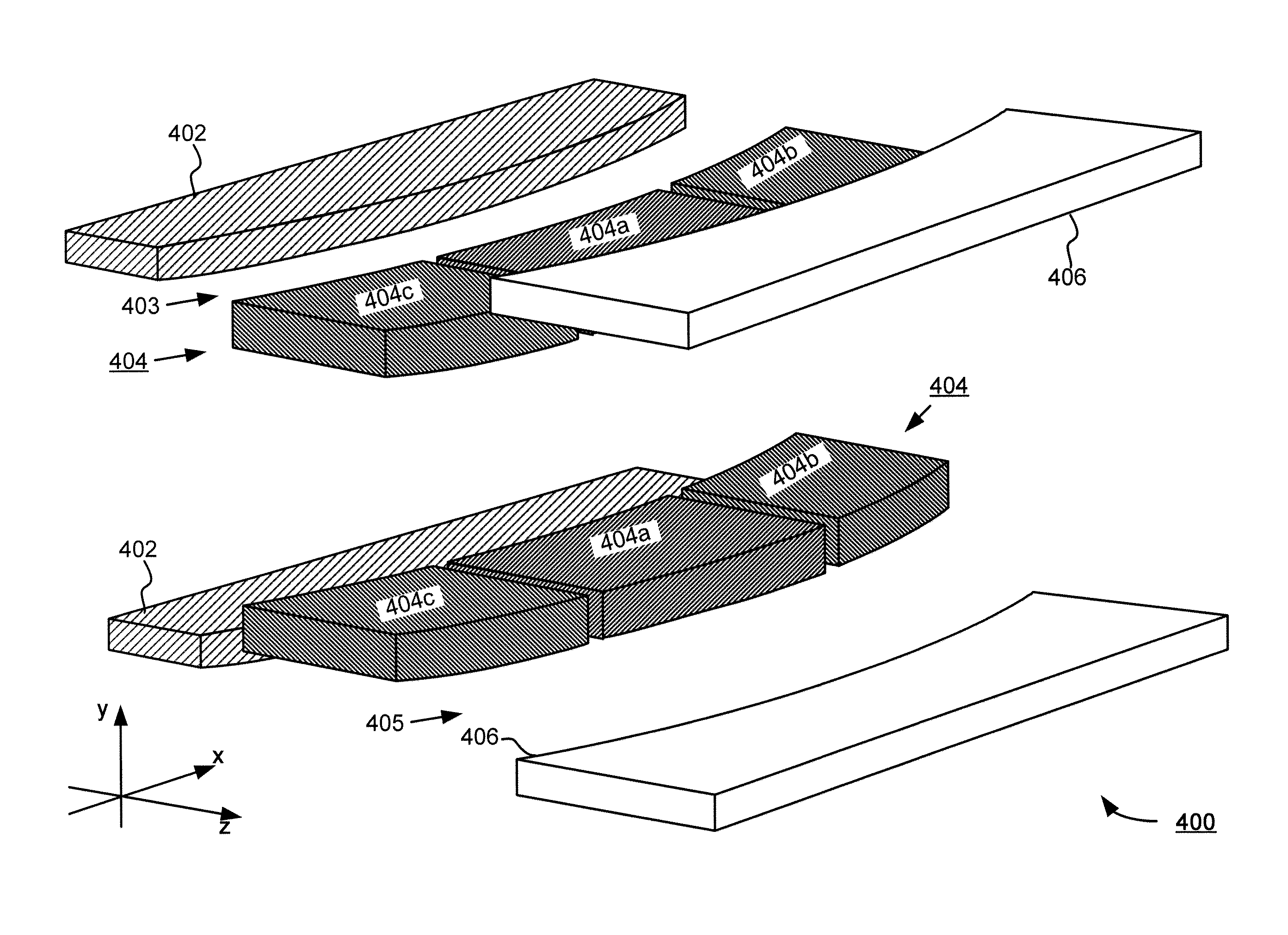
[0046] Embodiments of the present disclosure illustrate an improved type of electrostatic lens that has one or more segmented suppression electrodes. These electrodes may comprise multiple segments that are independently or separately biased with respect to one another thereby providing flexible and effective manipulation of an ion beam's shape as well as its energy.

[0047] Referring to FIG. 4, there is shown a perspective view of an electrostatic lens 400 in accordance with an embodiment of the present disclosure. Somewhat similar to a conventional electrostatic triode lens, the electrostatic lens 400 may comprise an entrance electrode 402 and an exit electrode 406. Instead of a single suppression electrode, however, the electrostatic lens 400 may comprise a plurality of electrodes (collectively referred to as “suppression electrode 404”) between the entrance electrode 402 and the exit electrode 406. In other words, what used to be a single suppression electrode may be segmented in...


PUM


Abstract

A technique for shaping a ribbon-shaped ion beam is disclosed. In one particular exemplary embodiment, the technique may be realized as an apparatus for shaping a ribbon-shaped ion beam. The apparatus may comprise an electrostatic lens having a substantially rectangular aperture for a ribbon-shaped ion beam to pass through, wherein a plurality of focusing elements are positioned along short edges of the aperture, and wherein each focusing element is separately biased and oriented to shape the ribbon-shaped ion beam.

Description

CROSS-REFERENCE TO RELATED APPLICATIONS [0001] This patent application is a continuation-in-part of U.S. patent application Ser. No. 11 / 413,570, filed Apr. 28, 2006, which claimed priority to U.S. Provisional Patent Application No. 60 / 736,293, filed Nov. 15, 2005, each of which is hereby incorporated by reference herein in its entirety.FIELD OF THE DISCLOSURE [0002] The present disclosure relates generally to ion implantation and, more particularly, to a technique for shaping a ribbon-shaped ion beam. BACKGROUND OF THE DISCLOSURE [0003] Ion implanters are widely used in semiconductor manufacturing to selectively alter conductivity of materials. In a typical ion implanter, ions generated from an ion source are directed through a series of beam-line components which include one or more analyzing magnets and a plurality of electrodes. The analyzing magnets select desired ion species, filter out contaminant species and ions having incorrect energies, also adjusting ion beam quality at a...

Claims


Application Information

Patent Timeline
IPC IPC(8): H01J37/12
CPCH01J37/12H01J37/3007H01J2237/121H01J2237/083H01J37/3171H01J37/30H01J37/317
Inventor RADOVANOV, SVETLANA B.KELLERMAN, PETER L.BENVENISTE, VICTOR M.LINDBERG, ROBERT C.PURSER, KENNETH H.ROCKWELL, TYLER B.BUFF, JAMES S.RENAU, ANTHONY
Owner VARIAN SEMICON EQUIP ASSOC INC
Why Eureka
Try Eureka