Self-Aligning Former Assembly

a former assembly and self-aligning technology, applied in the direction of packaging, transportation and packaging, successive articles, etc., can solve the problems of malformed packages, incomplete seals, and difficult and time-consuming tasks of aligning formers, especially with pull-down belts and longitudinal seam formers

Inactive Publication Date: 2008-09-25
J & F BUSINESS
View PDF26 Cites 11 Cited by
  • Summary
  • Abstract
  • Description
  • Claims
  • Application Information

AI Technical Summary

Benefits of technology

[0009]A self-aligning former assembly has a single-point mount for attachment to an automated packaging machine. In one preferred embodiment, substantially rectangular apertures are configured to fit snugly on a plurality of substantially rectangular shoulders formed on a mounting post. This configuration inhibits any pivoting motion of the former on the mounting post. Other aperture shapes and shoulder shapes which resist rotation about the mounting post may be employed. In one particular preferred embodiment, the mounting post is attached to a base plate with a plurality of spaced-apart fasteners to prevent rotation of the mounting post on the base plate. Radial attachments may be used to secure the funnel portion of a product feed tube to the mounting apparatus. Paired upper and lower mounting brackets permit precise alignment of the device prior to affixing the radial attachments to the mounting brackets. The mounting system of the invention obviates the need for adjusting the former on the packaging system to align the former assembly with the pull-down belts and the longitudinal seal former.

Problems solved by technology

In the past, aligning the former particularly with the pull-down belts and longitudinal seam former was a difficult and time-consuming task.
Even a slight misalignment between the former and the rest of the packaging system can result in malformed packages and / or incomplete seals.

Method used


Image

  • Self-Aligning Former Assembly
  • Self-Aligning Former Assembly
  • Self-Aligning Former Assembly

Examples


Embodiment Construction

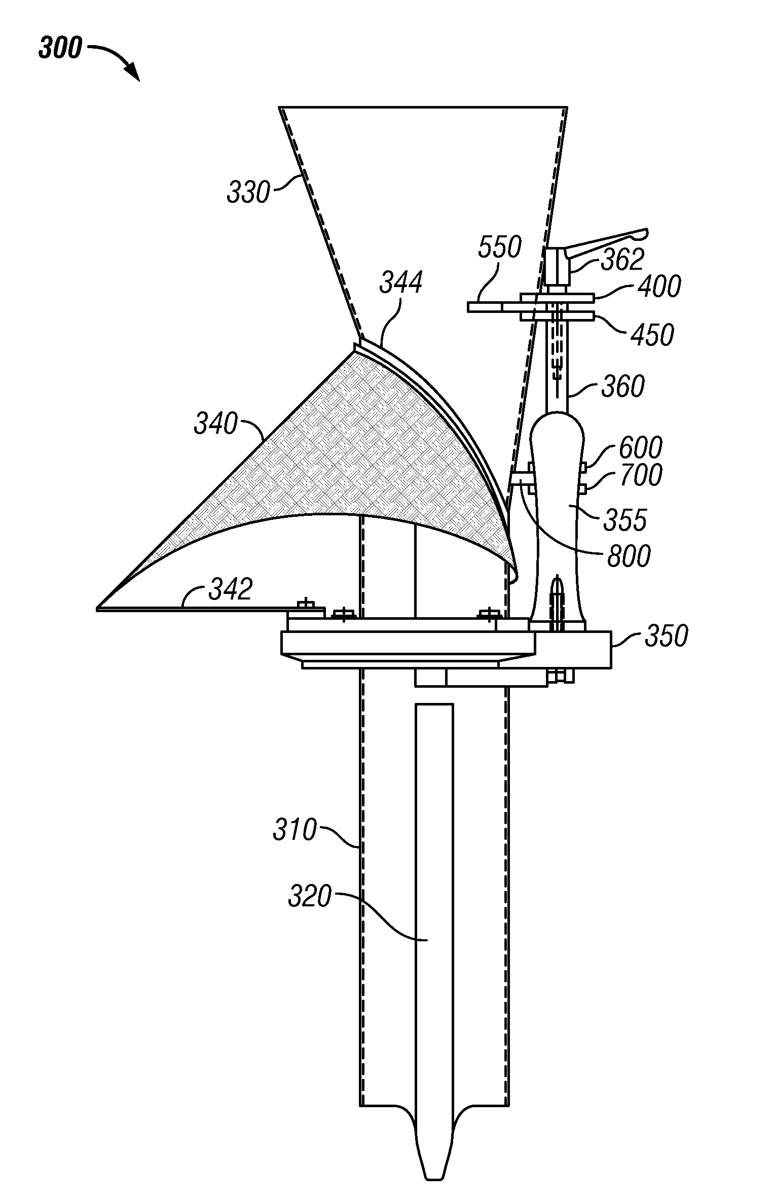
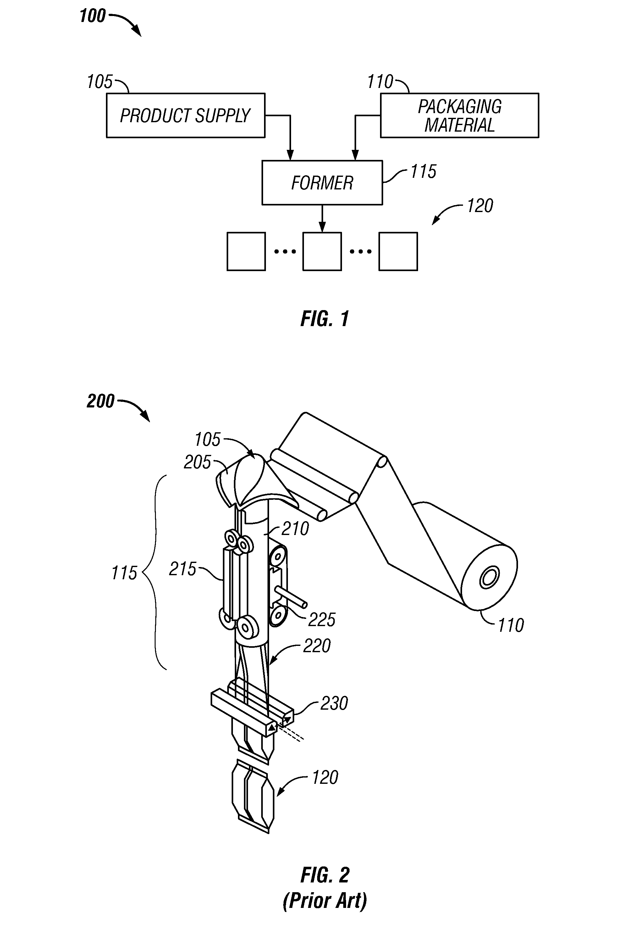
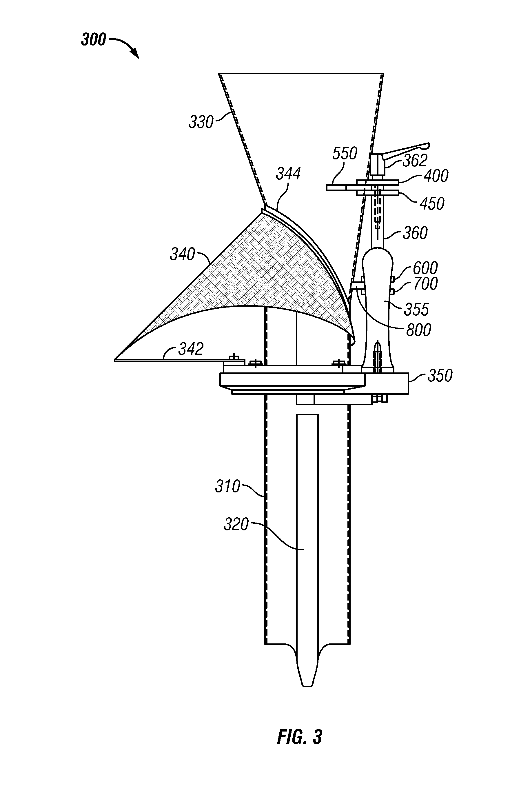
[0021]The invention may best be understood by reference to the embodiment illustrated in the drawing figures. In the side elevation of FIG. 3 and the front elevation of FIG. 4, a former assembly 300 according to the present invention may be seen to comprise a generally cylindrical fill tube 310 whose upper portion may have a progressively expanding diameter so as to form funnel section 330 which facilitates entry of product into fill tube 310. Fill tube 310 may also comprise one or more flat sections 320 for increasing the contact area between pull down belts and bagging material [not shown] and / or section 322 for backing longitudinal seam sealer 215 when the former assembly 300 is installed in an automated packaging machine such as that illustrated in FIG. 2.

[0022]Base plate 350 provides structural support for the other components of former assembly 300 and may be equipped with conventional means for mounting the assembly on an automated packaging machine. One or more handles or ha...


PUM

PropertyMeasurementUnit
aspect ratioaaaaaaaaaa
flexibleaaaaaaaaaa
rigidaaaaaaaaaa

Abstract

A self-aligning former assembly has a single-point mount for attachment to an automated form / fill / seal packaging machine. Substantially rectangular apertures in a plurality of mounting brackets are configured to fit snugly on corresponding substantially rectangular shoulders formed on a mounting post. The configuration inhibits pivoting motion of the former on the mounting post. In an illustrated embodiment, the mounting post is attached to a base plate with a plurality of spaced-apart fasteners which prevent rotational movement of the mounting post relative to the base plate. Radial attachments are used in the illustrated embodiment to secure the funnel portion of a product feed tube to the mounting apparatus. Paired upper and lower mounting brackets permit precise alignment of the device prior to affixing the radial attachments to the mounting brackets. The disclosed mounting system obviates the need for subsequent adjustment of the former on the packaging system to align the former assembly with the pull-down belts and the longitudinal seal former.

Description

BACKGROUND OF THE INVENTION[0001]This invention relates generally to product packaging systems. More particularly, it relates to formers used on automated equipment to configure sheet material into individual bags and fill the bags so formed with product.[0002]For speed and economy of operation, the automated form / fill / seal type of bagging system is often chosen for bulk products, particularly foodstuffs. Material in sheet form (for example, a pre-printed, aluminized polymer sheet; TYVEK® spunbonded olefin, a synthetic material made of high-density polyethylene fibers; woven or knitted fabric material comprising natural fibers, synthetic fibers or a blend of natural and synthetic fibers; paper, including coated papers; cardboard and metal foils) is formed into a tube shape, provided with a longitudinal seal, filled with product and then sealed transversely to provide a closed bag. Such a process may be performed with continuous or near-continuous movement of packaging material throu...

Claims


Application Information

Patent Timeline
Patent Type & Authority Applications(United States)
IPC IPC(8): B65B61/00
CPCB65B2220/10B65B9/22
Inventor DOMINGUEZ, JOHN
Owner J & F BUSINESS
Why Eureka
Try Eureka